ECE 421L - Lab 7
John Huang
Huangj19@unlv.nevada.edu
Spring 2015
This lab will utilize the ZVN3306A and ZVP3306A mosfets.
We are to design an audio amplifier with the frequency range from 100Hz to 20kHz.
We are limited to use one 10uF capacitor and one 100uF capacitor.
We are going to be using a 10V supply voltage and an 8-ohm speaker.
First we are going to start with a use a push-pull amplifier.
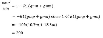
From previous labs we know the gain of a push-pull amplifier.

The starting schematic given to us by Dr.Baker.

We did our experiment by actually connecting a auxiliary cable to my phone in order to test our amplification.
Therefore our source signal would be where the VS voltage source is currently at.
Due to this fact, we are not exactly sure what voltage and at what the frequency the music was playing.
Doing a sim of this basic set up we can see that our output is only half of the original input.

As sugguested by Dr.Baker we added a source follower so that the impedance will be closer to the impedance of the speaker.

However this gave us a smaller gain.

Here we decided to place another push-pull amplifier to try and amplify the signal more before going into the speaker.

We can see even though the signal is distorted, we did hear an increase of our music signal being played through the speaker.

Just
for experimental purposes we decided to keep increasing the gain of the
signal by cascading more push-pull amplifiers until we could really
hear the music through the speaker.
We decided that at 5 push-pull amplifiers in cascade the volume of the music through the speaker was loud enough.
However when I simulated this procedure the output was railing and distorted.


Input resistance:
We can see that the input resistance is 10k ohms.

Output resistance:
We can see that the output resistance varies from 6 to 4 ohms depending on the frequency.

Power dissipation:
We noticed that putting 10V through the transistors was a very big value, we even had some problems of fried mosfets..
However we know that P=V*I
Based on our simulations we were pulling around 200mA of current through the speaker.

Therefore we can assume that the power dissipation from our amplifying circuit is about 2Watts.
Output swing:
Here when we have 5 push-pull amplifiers in cascade, we have a total output swing of 2.8V.

Conclusion:
Even
though the simulations have plenty of distortion, we were able to get a
reasonable listening level from such a small speaker by cascoding the
amplifiers in order to keep amplifying the signal.
I
do not think this is the best method that can be designed, however at
the moment it was the only experiment that was giving us results in
terms of volume of output.
We
also did not use an function generator in order to produce the signal,
therefore we did not opt to use an oscilloscope to measure output and
input and see it's waveforms.
We validated our results based on our ears and listening to the volume level of the music through the speaker.
Back up:
Make
sure you back up your whole CMOSedu folder with all your labs by
compressing the folder and sending it to yourself through email.

Return to my lab reports
Return to student lab reports
Return to ee420L webpage