ECE 421L - Lab 5
Here is the datasheet associate with the op-amp LM324.
For our experiments we will be using VCC+ = +5V and VCC- = 0V.
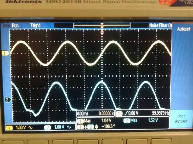
In our oscilloscope graphs, probe 1 is input while probe 2 is output.
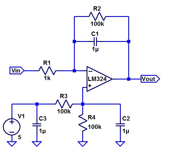
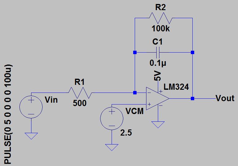
Circuit that we are using in our experiment:
1. In order to calculate the frequency response in the circuit, we can neglect the R2 resistor.
This is because it is chosen to be a big value so it can nullify the DC offset in our op-amp.
Vin/R1 = -Vout/(1/jwC1) = -Vout*2*pi*f*C1
Vout/Vin = -1/(j*2*pi*C1*R1) = -1/(j*2*pi*f*10e-3)
Gain = |Vout/Vin| =-1/(2*pi*f*10e-3)
phase |Vout/Vin| = pi/2
To find fun (unity gain frequency) we have to set |Vout/Vin| = 1.
Note that our integrator will work without the 100k resistor if removed.
The resistor is in the place just to adjust the offset of our integrator.
This will not affect our frequency response big a significant amount.
2.To verify our calculations we used a random frequency and calculated our Gain.
The results are as follows, note that our Vin = 1.04V.
F = 100Hz Gain=1.59V; Experimental Gain= 1.46V
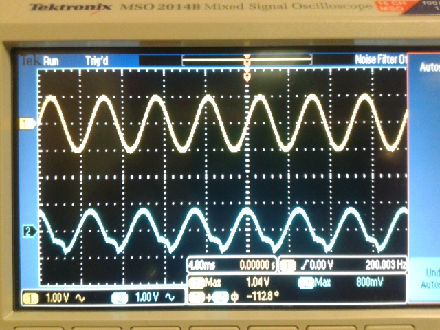
F= 200Hz Gain=0.769V; Experimental Gain= 0.769V
F=500Hz Gain=0.318V; Experimental Gain=0.385V
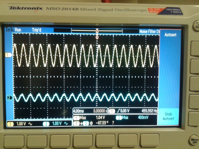
F=159kHz=Fun Gain=1V; Experimental Gain=1V
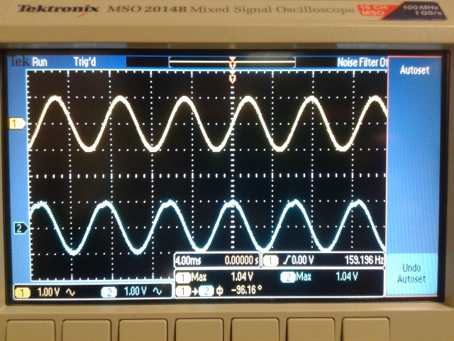
We can see that both the peak values of our input and output are at the same value.
From above you can see that our phase we measured varried from 87.59 to 112.8 degrees.
If I average the 4 measurements we took, it comes out to 100 degrees which is close to the theoretical 90 degrees.
We expected this phase shift because of our calulations from part 1.
3. Square-wave to triangle wave generation circuit.
This is basically done using an integrator, we used LM324 for the op-amp once again.
We can calculate our resistor and capacitor values from the equation:
delta V = (Vin*T)/(2*C1*R1)
Here we are using our input and output frequency as 10kHz, and our output ramp must swing from 1 to 4V, centered at 2.5V.
T = 1/f = 1/10kHz = 100us. delta V = 4-1 = 3V. Our centered is configured to have our VCM at 2.5V.
We used the capacitor values of 0.1uF and calculated our resistance.
R = (Vin*T)/(2*C*deltaV)
= (2.5*100us)?(2*0.1uF*3) = 417 Ohms
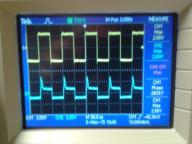
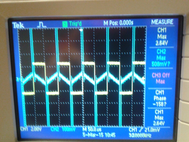
Unfortunately our experiment did not look too much like a triangle wave.
I expect this is because of the capacitor value that we picked causing the rise time and fall time to be very short.
However If we calculate the rise time and fall time using the standard equation it would be 40us.
Clearly from our graph we did not have a rise time of 40us.
We did however do some fiddling around with resistor values and frequencies to see if we could get a better triangle wave.
First we decided to swap our the resistor with a 15k resistor.
Then we changed the frequency to 1kHz.
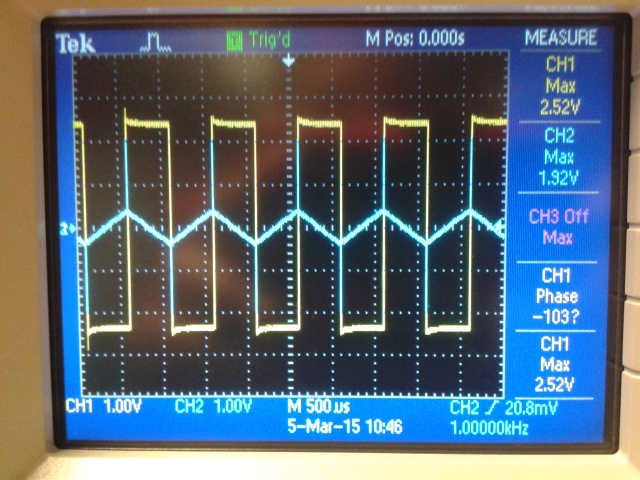
This lead us to a nice triangle wave, even though the components did not match the theoretical calculations.
Perhaps a good balance of a capcitor value and resistor value would to pick something that could potentially give us a higher yield.
We can pick a bigger capacitor and see if the rise time and fall time would change.
Conclusion:
From the experiments we derived the equation for gain with a capacitor in the feedback.
We saw that the resistor in parallel to the capacitor does not affect the gain, it is only needed to nullify the DC offset.
We know how to generate a triangle wave from a square wave using an op-amp integrator.
We also know how to pick values with a given criteria to generate the triangle wave.
Back up:
Make sure you back up your whole CMOSedu folder with all your labs by compressing the folder and sending it to yourself through email.