ECE 421L - Lab 4
John Huang
Huangj19@unlv.nevada.edu
Spring 2015
Lab description:
Lab 4 is to learn about the gain-bandwidth product using the LM324 op-amp.
Using the GBP we can find the BW for non-inverting and inverting op-amps.
We will also look the slew rate of the LM324 op-amp.
In the lab we will ultilize the LM324 op-amp.
Here is the datasheet associate with the op-amp LM324.
For our experiments we will be using VCC+ = +5V and VCC- = 0V.
In our oscilloscope graphs, probe 1 is input while probe 2 is output.
1. Using the datasheet, I estimated the bandwidths for the non-inverting op-amp topologies.
We can see that the unity gain frequency (Fun) is 1.3MHz.

BW = Fun/AOL.
| Gain | Theoretical Bandwidth |
| 1 | 1.3MHz |
| 5 | 260KHz |
| 10 | 130KHz |
2.Experimentally verify these estimates using a common-mode voltage of 2.5V.
For the noninverting topology, we used the forumula. Gain = 1 + RF/RI.
We also connect the input to the Vplus side since it is noninverting.
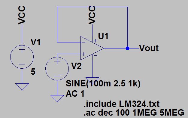
Schematic of Gain 1:
Since we needed a gain of 1, we just used a wire to connect the output and the negative terminal together.
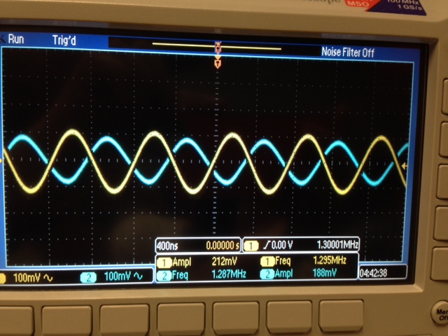
Experimental Results of Gain 1:
We can see that the input is 212mV and ouput is 188mV. This is a very close gain of 1 for the output.
You can also see that our bandwidth frequency is approximately 1.3MHz.
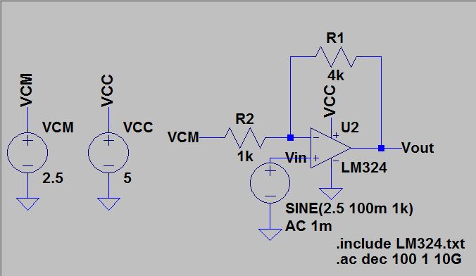
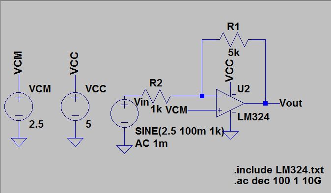
Schematic of Gain 5:
We used RF as 4k and RI as 1k to get a gain of 5.
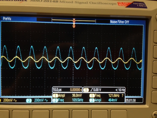
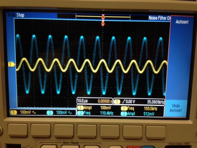
Experimental Results of Gain 5:
Our input is at 96mV while our output was at 464mV, which is very close to a gain of 5.
For our bandwidth frequency we measured at 110KHz.
Schematic of Gain 10:
We used RF at 9k and RI at 1k to get a gain of 10.
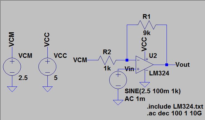
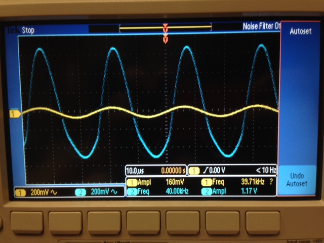
Experimental Results of Gain 10:
Our input was 160mV while our output was 1.17V. This is roughly a gain of 10.
Our bandwidth frequency measured was 40KHz.
Differences:
| Gain | Experimental Bandwidth | Theoretical Bandwidth | Difference |
| 1 | 1.3MHz | 1.3MHz | 0 |
| 5 | 110KHz | 260KHz | 150KHz |
| 10 | 40KHz | 130KHz | 90KHz |
As you can see from above that have differences in our experimental and theoretical bandwidth.
This can be caused by the fact that we are only using a VCC input of 5V while in the data table it is measured at 30V.
Compared to using 5V, 30V would be able to boost the gain much more effectively thus giving us a better result.
We also did not consider any possible noise from the input or ground in our experiment.
3. Repeated experiment for inverting op-amp topology.
BW = Fun/(|AOL|+1).
| Gain | Theoretical Bandwidth |
| -1 | 650KHz |
| -5 | 217KHz |
| -10 | 118KHz |
For the inverting topology, we used the forumula. Gain = -RF/RI.
We also moved the input to the Vminus side since it is inverting.
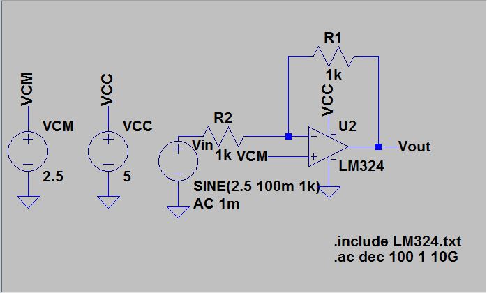
Schematic of Gain -1:
We used RF as 1k and RI as 1k to obtain a gain of -1.
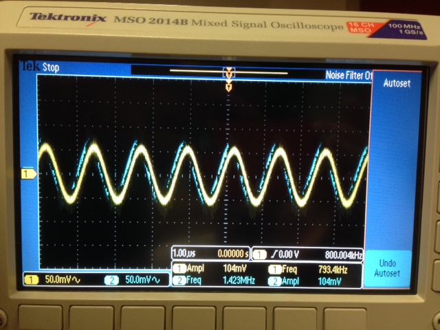
Experimental Results of Gain -1:
Our input was 104mV while our output was 104mV. This is a gain of 1.
However our output should have been out of phase by 180 degrees in order to get an output of -1.
You can see that it is not exactly in phase but this comes with experiemental results.
We measured a bandwidth frequency of 800KHz.
Schematic of Gain 5:
We used RF as 5k and RI as 1k to get a gain of -5.
Experimental Results of Gain -5:
Our input was 100mV while our output was 512mV.
We can see that the input and output are also out of phase, giving us a gain of -5.
Our measured bandwidth frequency was 110KHz.
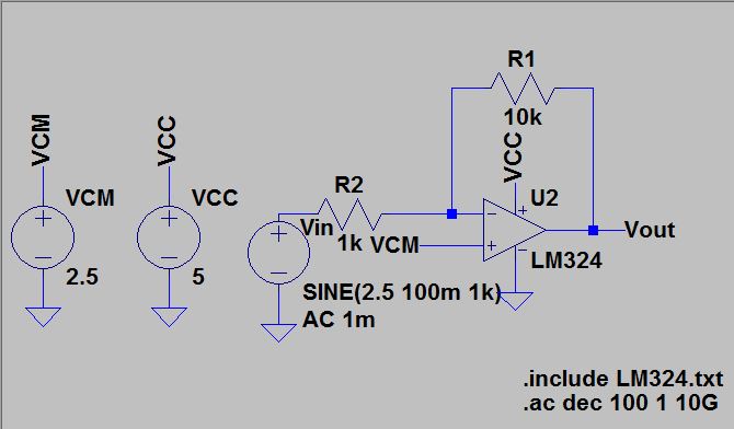
Schematic of Gain 10:
We used RF as 10k and RI as 1k to get a gain of -10.
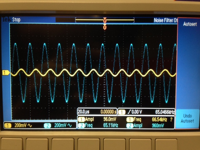
Experimental Results of Gain -10:
Our input was 96mV while our output was 960mV.
We can also see that our input and output is out of phase, giving us a gain of -10.
Our measured bandwidth was 65KHz.
Differences:
| Gain | Experimental Bandwidth | Theoretical Bandwidth | Differences |
| 1 | 793KHz | 650KHz | 143KHz |
| 5 | 110KHz
| 217KHz | 117KHz |
| 10 | 65KHz
| 118KHz | 53KHz |
Just as we had differences in our noninveting we also have the same with our inverting.
This
can be caused by the same problem from the noninverting that we are
only using a VCC input of 5V while in the data table it is measured at
30V.
4. To measure the slew rate of the LM324 we used a sinewave and a pulse wave as input.
We can see from the datasheet that our slew rate is about 0.4V/us.

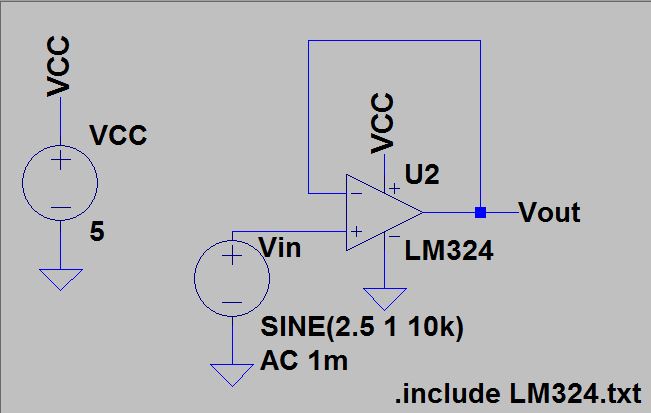
Our schematic to measure our slew rate using a sine wave input:
We used the noninverting op-amp topology without any resistors.
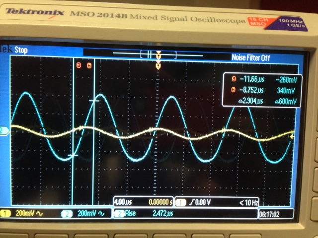
Experimental results:
In
order to obtain the slew rate, we needed to measure the voltage at 10%
and 90% of the output using cursors and calculate the difference.
We also needed to measure the rise time of the output, this was done using the measurement option on the oscilloscope.
We can now calculate our experimental slew rate.
SR = voltage difference / rise time = 600mV / 2.904us = 0.243V/us.
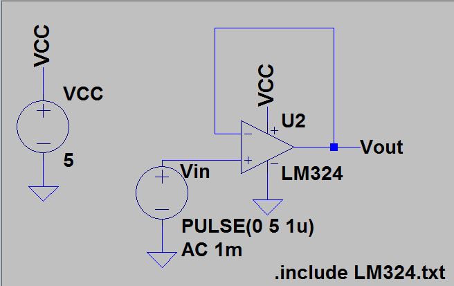
Our schematic to measure slew rate using a pulse input:
We also used the noninverting op-amp topology without any resistors for our pulse wave input.
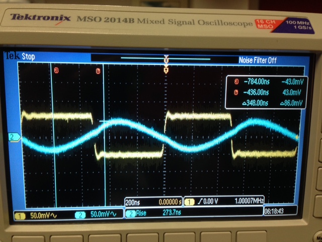
Experimental results:
We measured the voltage difference and rise time the same as the previous experiment.
SR = 86mV / 348ns = 0.247 V/us.
Differences:
| Theoretical | Sine wave | Pulse wave |
| 0.4 V/us | 0.243 V/us | 0.247 V/us |
Our experimental slew rate for both the sine and pulse wave are very close to each other.
However they are not close to the theoretical value.
This can be caused by the way I constructed the experiment, there could have been a better way to measure the slew rate.
The
measurement for 10% and 90% of the output was also not very accraute
since we could not actually see the percent of voltage on the
oscilloscope.
Even though it is slight, we can see that the pulse wave experiment has a closer slew rate value to the theoretical.
This could be because the way we derive the slew rate is the derivative of the voltage change with respect to time SR = dv/dt.
We
can see that the pulse wave's voltage only changes on it's rising or
falling edge compared to the sine wave which is continously rising or
falling.
Over all we can say that measuring the slew rate with a pulse wave can be more effective compared to a sine wave.
Conclusion:
From the experiments we are able to calculate the bandwidth frequency based on the unity gain frequency and it's gain.
We can see that the experimental results almost always differ from the theoretical results.
This can be caused by user error or manufactor error. We also have the consider our experimental limitations with equitment.
The important notes to take away from this lab is the GBP and how it relates to the Fun and the AOL.
The
topology of inverting or noninverting is not as important when looking
at the bandwidth frequency since when you have a really high gain the
frequency is relatively close.
Back up:
Make
sure you back up your whole CMOSedu folder with all your labs by
compressing the folder and sending it to yourself through email.
Return to my lab reports
Return to student lab reports
Return to ee420L webpage