ECE 421L - BGR Project
For this lab we will be using the CD4007 CMOS transistor array.
The models we used for all our simulations can be found here.
All the simulations for our project can be downloaded here.
Using as many diodes, resistors, capacitors, and CD4007 chips we are to build a bandgap voltage reference (BGR).
We designed our BGR based off Chapter 23 from the CMOS book.
The BGR design is formed using the CTAT and PTAT references.
One of the main aspect when designing a BGR is making sure that your voltage is constant across each side, therefore we need a constant current through each side.
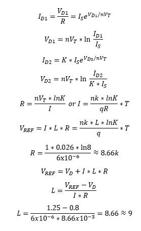
The basic CTAT will provide us a current mirror and our CTAT was already built from lab 9, all we had to do was calculate the resistor (R) and how many (K) diodes we needed.
We decided to build a BGR for 5-15V with a Vref of 1.25V with a current draw of 50uA using 8 diodes in parallel (using 8 since ln(8)=2 to simplify the math)
Using the equations in the book and VD to be 0.8V and VT to be 26mV we got R to be 1k and L to be 9.
Simulating the Vref as temperature changes we get the following.
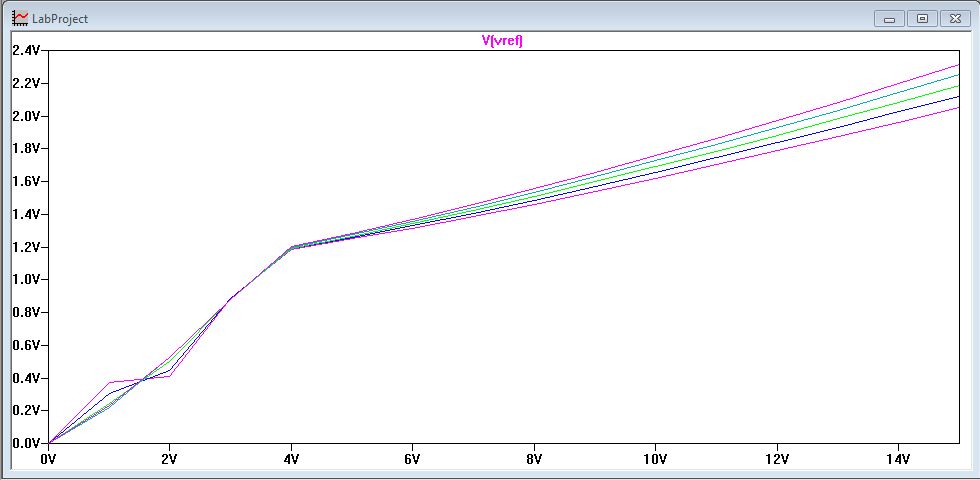
We can see that the temperature does not really affect Vref that much as it is increase from 0 to 100C.
Now to experimentally verify our results.
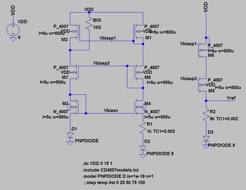
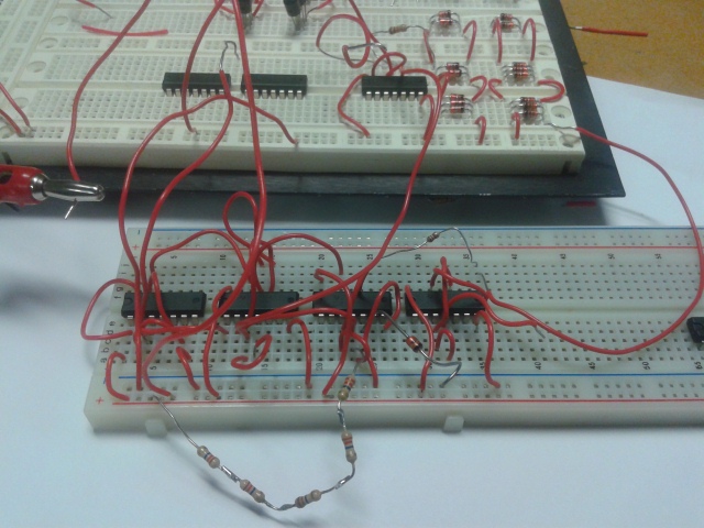
Below is our BGR circuit.
We decided to use a multimeter to measure Vref as we swept VDD.
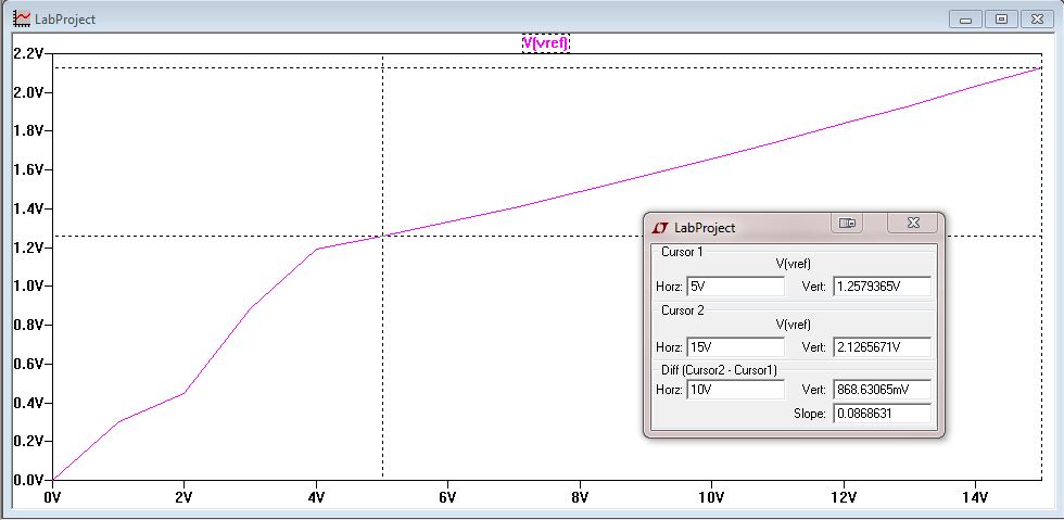
For our experiment we swept VDD from 0 to 15V.
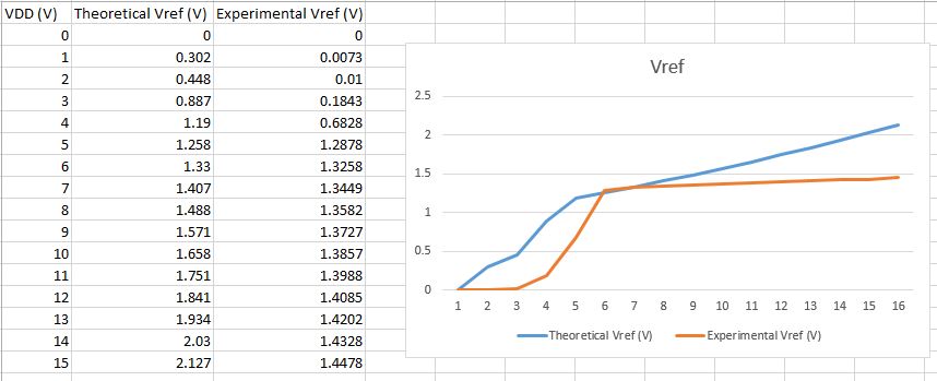
Below is the recorded voltages on an excel sheet.
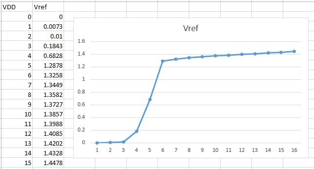
We can see that at 5V our Vref becomes 1.29V which is close to our 1.25V design.
Unlike our simulation, as we increased VDD to 15V we only increase Vref by 160mV.
Below is all the pictures of our multimeter when we measured Vref.
| VDD (V) | Vref | VDD (V) | Vref |
| 1 | 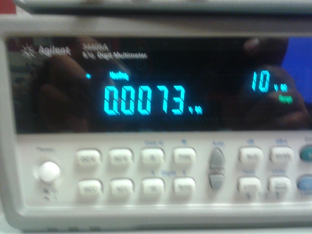 | 9 | 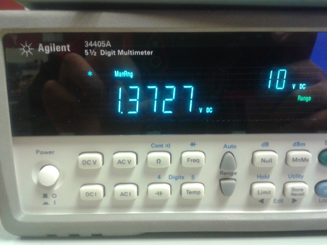 |
| 2 | 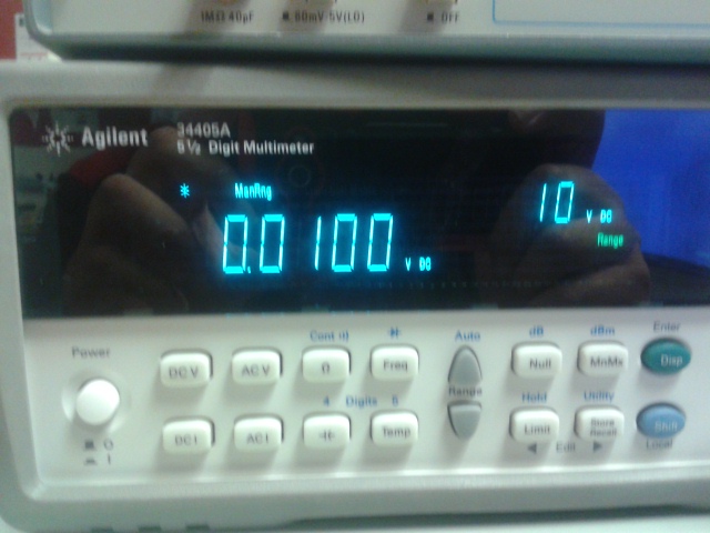 | 10 | 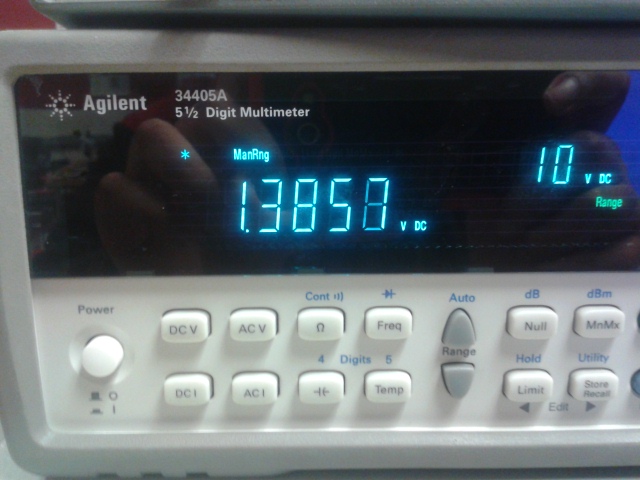 |
| 3 | 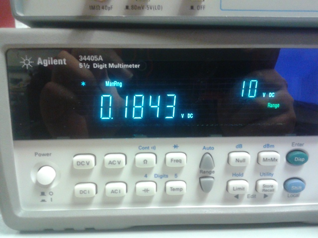 | 11 | 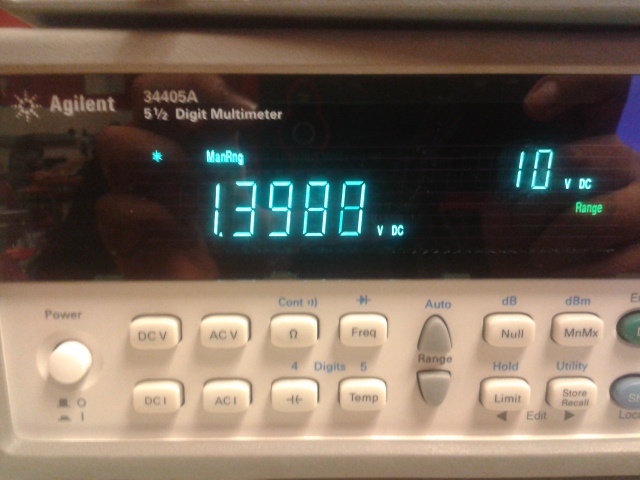 |
| 4 | 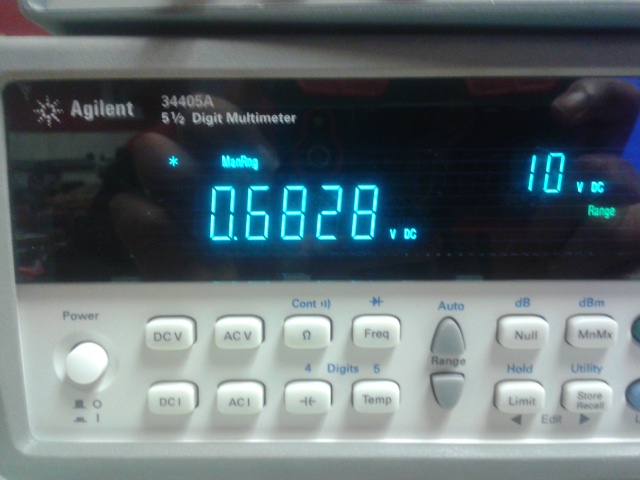 | 12 | 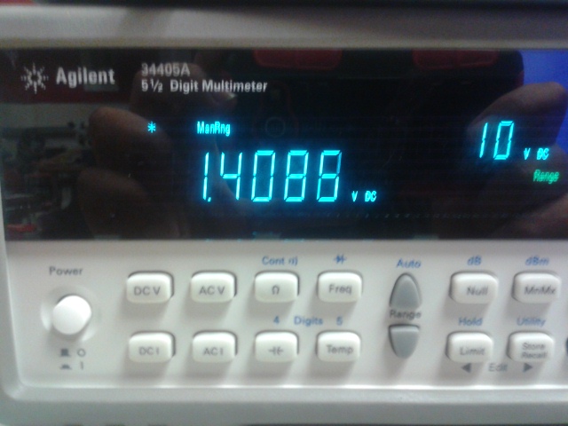 |
| 5 | 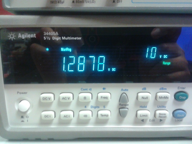 | 13 | 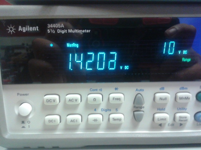 |
| 6 | 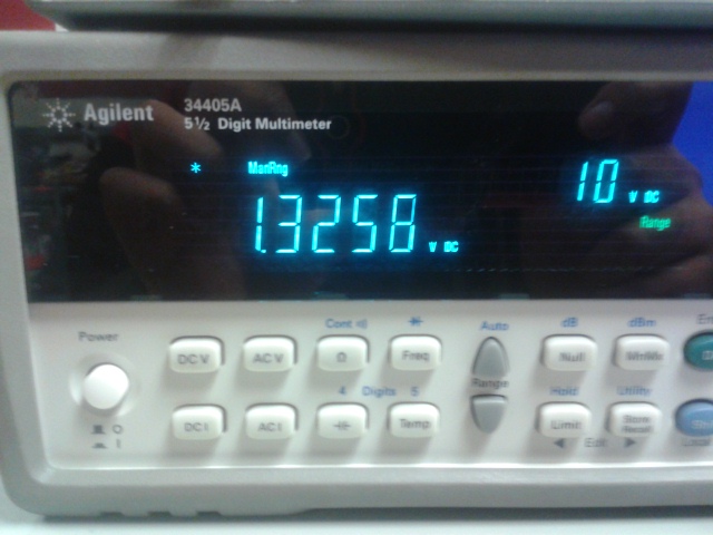 | 14 | 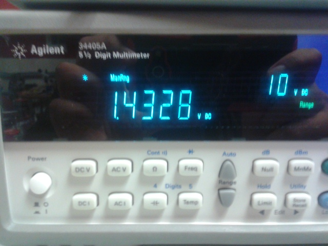 |
| 7 | 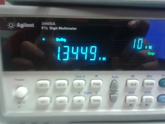 | 15 | 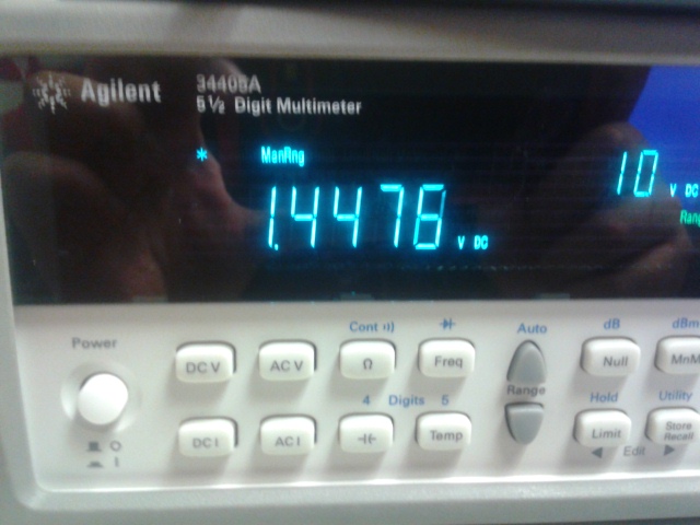 |
| 8 | 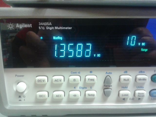 |
Now comparing the simulation and experimental results.
Conclusion:
We originally use our BMR that we design in lab 9 however it was not producing enough voltage. We tried varying different resistor values and different type of diodes, however we could not get our voltage past 1V.
After asking Dr. Baker on how we can increase our voltage, we were told to use a cascode BMR to increase the current. We however made our BMR cascode with both PMOS and NMOS and was still getting under 1V.
It was only until later when we asked Dr. Baker once again and he told us to remove the NMOS cascode and keep the PMOS cascode. Only after this we got a little over 1V for our Vref, then we were able to verify the rest of the measurements.
From everything, our band gap reference actually came very well. Even our experimental and simulation results were pretty accurate to what we expected.
After another long semester, we are finally done! Can't say it was not hard but atleast we learned.
Thank you Dr. Baker
Backup: