Lab
7 - EE 420L - Design of an Audio Amplifier
Pre-lab work
Introduction
This
lab required us to design an audio amplifier with the knowledge that we
have gained from our previous labs. We are allowed to use as many
resistors and transistors as we desire along with only one 10uF and one
100uF capacitor. Audio amplifiers must operate with large voltage
swings, low output impedance, and in the frequency range from 10-20kHz.
The Push
Pull
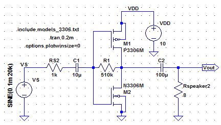
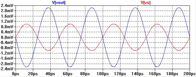
At first using,
using a resistor of 100k had too much gain for
our 10mV input voltage so we decresed the resistance to allow for a
lower gain.
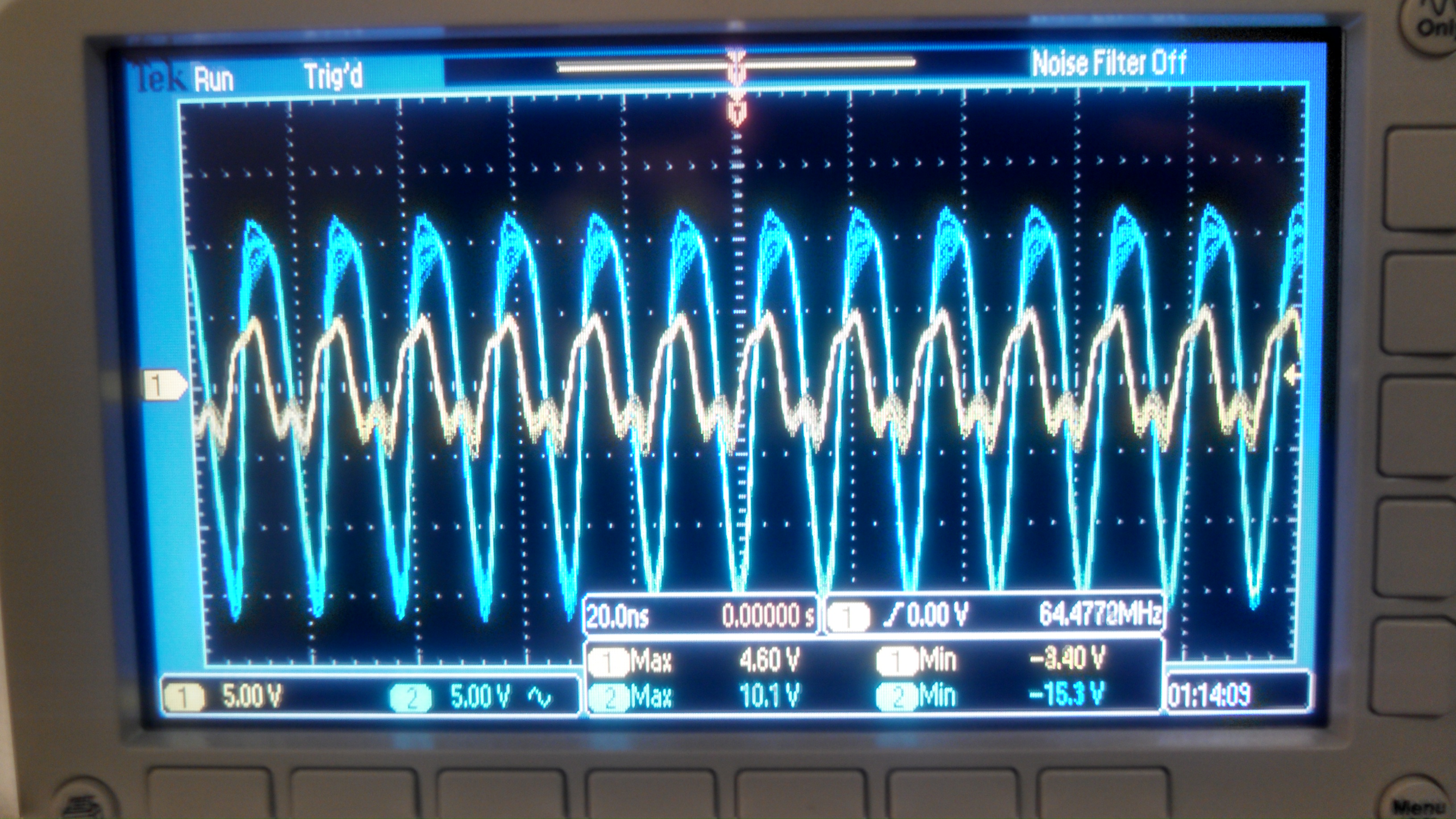
Output Swing
Our output swing ranged from +10V to -15V
Power Dissipation
With VDD is 10V and our current near 250mA => power = 2.5 Watts.
Input Resistance
The
input resistance depends entirely on our resistor value in series
with 1/gmn || 1/gmp. With 1/gmn~=1/gmp~=56, Rin = 510+23~= 510 (the
value of the resistor used).
Output Resistance
The
output resistance depends on R || 1/gmn || 1/gmp ~= 1/gmn||1/gmp ~= 23
ohms. This needs to be near 8 ohms to properly drive our 8 ohm speaker.
With this load, we see a large voltage drop across the output
resistance leaving only 25.8% of the voltage left for the speaker. For
louder sound, we need either more gain or much lower output resistance.
Conclusion
We designed an audio amplifier
capable of accepting input from an aux cord and driving an 8 ohm small
speaker using a basic push pull amplifier configuration.
Return
Return to EE420L Student
Directory
Return to EE420L
Page
Return to CMOSedu