Lab 5 - EE 420L - Op-amps III, the op-amp integrator

Jonathan K DeBoy
deboyj@unlv.nevada.edu
27 February 2015


Pre-lab work


Introduction

This lab served as an introduction to Operational Amplifiers and their use as an integrator. This configuration can be used in a multitude of situations which may require envoloping or preparing signals for sampling and processing.


Experiment 1 - Integrator frequency response


fig1.jpg

We implimented the above integrator and achieved the below waveform. We found that frequencies any higher than around 100MHz really killed the waveform, causing discontinuities and overall lower amplitude in the output.

 fig1.jpg     fig1.jpg

We used our hand calculations (below) to determine both the frequency response of our integrator. Solving that equation for 1 gave us the unity frequency of around 160Hz. The next waveform is our unity gain output. We can ignore R2 because it does not affect our analysis very much since R2 >> R1, most of the transient current will go through the capacitor anyway. It is needed to keep our DC gain finite: ACL = -R2/R1. So this resistor does not affect our frequency response very much. Our circuit will work if that guy is removed, but if the Vin is removed, our output will jump to our rails since R2 is missing.

fig2     fig1.jpg     fig3


Experiment 2 - Design of a traingle wave generator


We 
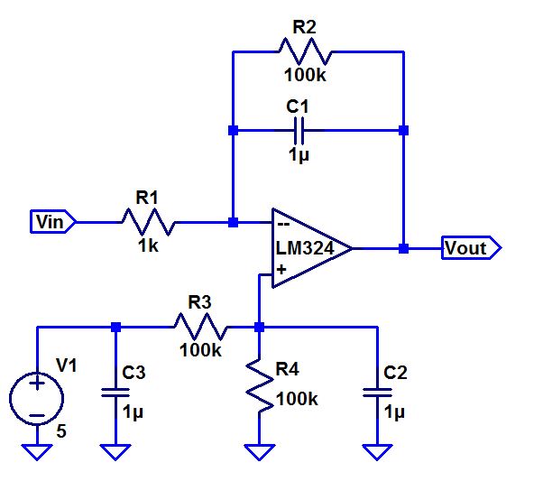
designed our integrator to accept a 2V peak to peak square wave. It will swing up and down by 2V peak to peak (unity gain) at a frequency of 10kHz. Plugging our values into the relationship Vc = 1/C Integrate[ Ic * dt], where Ic = Vin/R, we can set the capacitor to a particular value to solve for the R which we need. Initially choosing a C to be 1uF led to the use of a 100Ohm resistor (wayyy to low). So I went an order of magnitude lower to allow us to use a 50kOhm resistor instead with a much smaller capacitor. Our output below came close to what we designed. If we spent a lot more time messing with different R and C values, we could have gotten exactly 4V, but we felt 3.8 or so was accurate enough for this.

fig1.jpg     fig1.jpg


Conclusion


We explored the real characteristics of this LM324 op-amp such as its ability to act as an integrator. This type of circuit can be used whenever enveloping is needed or if we need to gerenate a particular waveform given a specified input, such as square to triangle converter, just like we designed in part 2.


Return
Return to EE420L Student Directory
Return to EE420L Page
Return to CMOSedu