Lab 3 - EE 420L - Op-amps I, basic topologies, finite gain, and offset

Jonathan K DeBoy
deboyj@unlv.nevada.edu
20 February 2015


Pre-lab work


Introduction

This lab served as an introduction to Operational Amplifiers and some of their inheirant flaws including voltage offsets, finite gains, and signal clippings.While these may be flaws compared to an ideal Op-Amp model, there is plenty of methods to use these charactaristics to a designer's advantage. We used the LM324 Op-Amp chip with our Vcc+ set to +5V and Vcc- set to 0.


Experiment 1

 
 fig1.jpg


Our VCM was set to 2.5V and it will not change due to our fixed voltage divider. This common mode voltage is used to center our output when we don't have a negative potential at our rails. If we set VCM to ground, we would be unable to produce negative voltage since we are supplied by a 0 to 5V power supply, causing our outputs to clip. If we set VCM to 2.5 (as we did), now we can have the full swing intended for our circuit centered at 2.5V. This offset can be eliminated on the O-scope by using AC coupling. The maximum ratings for the VCM is shown below (Vcc - 1.5) when VCC cannot exceed 30V.

Our ideal closed-loop gain is unity: ACL = Rf/Ri = 5k/5k = 1
Open loop gain is determined by the specs of the Op-Amp and frequency:

We can see that our unity gain bandwidth is 1MHz from the graph. 100db for DC which is about 100,000x gain.

Output swing is centereed about VCM or 2.5V. Whatever we attach to that positive terminal is where our output will be centered at.We would not get our full swing potential (2.5V amplitutde). Instead a signal that should be intact if we were centered about VCM would be clipped at one end because we are not centered about our rails (power supplied).
In our configuration of unity gain, a signal with an amplitude larger than 2.5 will get clipped because it will exceed the supplied voltage at the rails.
Then 250mV would be the maximum since the clipping is determined based of the output voltage in respect to the rails. (.25 * 10 = 2.5V swing + VCM = 5 and 0 = rails!)
The capacitors are meant to couple the Op-Amp. Any changes in ground or in the power supply will be mirrord (cap is a short for AC) in the Op-Amp and circuit, eliminating any noise.Not at all. Again these capacitors are meant to couple the Op-Amp to ground, killing any noise on ground or on the source.
If we were to use large resistors (such as MOhms or GOhms), then even this small current at 20nA will cause a voltage drop across the resistors (seen by the teminal as two resistors in parallel): 1V for 100MEG resistors (brought to you by Ohm's l.aw).


Experiment 2

  
  fig2.jpg
Explain how the above circuit can be used to measure the op-amp's offset voltage.
In this circuit, we force no current fo flow (ideally) since both sides of R1 will be at VCM. This way, any differences between the two terminals will be caused by the offset voltage alone. Because of this, we can measure the difference between the output voltage and each terminal, subtract them, and divide them by our ACL to get a emperically determined offset voltage for that partricular Op-Amp.

Experimental Data

Op-Amp Von Vop |Von-Vop| |Von-Vop| / A
1 7 mV 6.7 mV 0.3 mV 15 uV
2 11.2 mV 11.5 mV 0.3 mV 15 uV
3 7.4 mV 7.2 mV 0.2 mV 10 uV
4 2 mV 2.8 mV 0.8 mV 40 uV

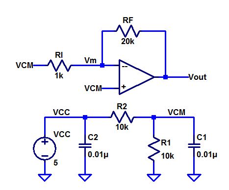
We could not measure the offset by subtractive Vm from Vp becuase of their 2.53V DC value. Instead we decided to use the multimeter to measure the potential difference between the output of the Op-Amp and the negative and positive terminal respectively. We then subracted those millivolt values for each amplifier and divided by our DC open loop gain (20x) to finally realize our Voffset. According to the datasheet, we should never have more than +/-5mV of DC offset and our experiments showed true to that, granted we didn't put the chip to an open flame or anything extreme so we got very modest offsets (10s of micro volts). Keep in mind that all of these different Op-Amps are from the same chip!


Conclusion


We reviewed basic Op-Amp analysis including how to find the closed loop gain ACL and how to loop up information on its datasheet such as frequency response and input bias currents. We experimentally determined the offset voltages for multiple Op-Amps, a tool useful for high precision applications.


Return
Return to EE420L Student Directory
Return to EE420L Page
Return to CMOSedu