
Lab 7 - EE 420L
1. Review the frequency response of Push-Pull amplifier.
2. The audio amplifier frequency ranges from 100Hz to 20kHz. The power supply is 10V.
3. Utilize some ZVN3306A and ZVP3306A MOSFETs, resistors and one 10uF and one 100uF capacitors to build up the circuit. The input resistance of the opamp, Rin, should be a few kiloohms, and the output resistance, Ro, should be less than 1ohm because the load speaker is only 8ohms.
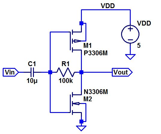
4. Please start from the push-pull amplifier characterized in lab6.
Finally, Don't forget to backup your report and work directory on your computer or dropbox and upload it to the CMOSedu.com for the future study and discussion.
1. Consideration of the audio opamp design. Because the load speaker is 8-ohm resistor. Actually the Ro of the push-pull opamp is ron||rop, so it's much larger than 8 ohms. Learning from the topology of CS opamp in lab6, we can use big capacitor to seperate the RL and the Ro. This method not only keeps the biasing unchanged but also makes Rout becoming smaller.
The input resistance should be a few kiloohms. A 10uF cap connected to the gate node divides the DC voltage going through to affect opamp biasing. Looking into the gate node, the input resistance is 1/gmn||1/gmp.
The audio amplifier aims to amplify the signal from an MP3 player. The maximum current for a MP3 player is 100uA. So we can use 1V sinewave @1kHz with 10kohms to represent the source signal.
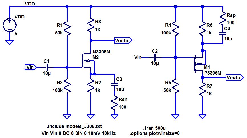
2. So based on the above considerations, the audio opamp is shown below. The output impedance is smaller than 8ohms. One 10uF cap connects to gates and one 100uF cap connect to the drains. Without the push-pull amplifier, the input signal with 10kohms directly connects to the 8ohms resistance. The output signal is zero.
If we use the pushpull amplifier, the output signal can be much higher to drive the 8-ohm load successfully.
3. We can see the simulation result of LTspice model. The output signal, Vout1, with push-pull amplifier is 1V from 0.5V input sinewave signal. The Vout2 is zero all the time. Without the help of pushpull amplifier, the MP3 signal cannot drive the 8-ohm speaker alone.

4. Build up the circuit (When VDD=10V, the output signal and input signal are disturbed by noise. So you can use 5V as VDD)
5. Power dissipation
The power dissipation of opamp is the division power between the sum of NMOS and PMOS power and load resistor power. So that means, at first, we need to find out the VDS or VSD for NMOS and PMOS respectively. Then from the datasheet, the drain current can be figured out. But when VDD=5V, the Id is hard to figure out from datasheet.
The following simulation result shows the dissipated current. The power dissipation is equal to 5V*60uA=300uW. And the DC drain voltage of PMOS and NMOS is about 1.9V. From the experimental result, the DC drain voltage is roughly 1.7V. That means, the experimental power dissipation is very close to 300uW.


output swing
The output swing for the designed push-pull opamp is +/-140mV.


input resistance
For the calculation of input resistance, we need to test the gate voltage at first. Then calculate the current through 10k resistor, so Iin=(1-Vg)/10k=(1-440mV)/10k=56uA. Thus Rin = 440mV/Iin=7.8kohms.

output resistance
In order to calculate the Rout, use two different load resistors: 8ohms and 10ohms. Get two different output voltages. Looking into output node, we can treat the opamp as voltage with a serial resistor byThevenin's theorem. So we can get
(Vout1-V)/iout1=Ro and (Vout2-V)/iout2=Ro. Thus the Vout1-iout1*Ro=Vout2-iout2*Ro. Based on the experimental result, I get Vout1=140mV, iout1=17.5mA. Vout2=200mV, iout2=20mA. So the output impedance is Ro=24.

Summary:
From above experiments, we study how to design an audio opamp.