
Lab 5 - EE 420L
Frequency response of the op-amp integrator
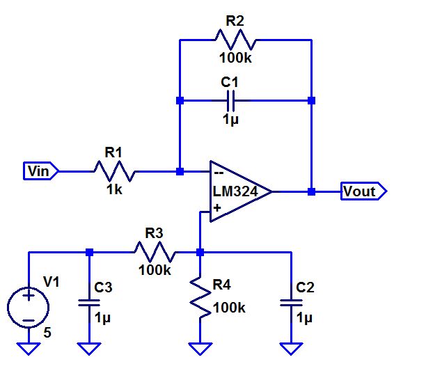
1. Hand calcualte the frequency response of the integrator and show the calculation steps.
2. Answer several questions: What can you neglect to simplify the calculation? Does the circuit work if you remove the 100k?Why? Does the 100k have much of an effect on the frequency response?
3. Use Experiment results to verify hand calcutions.
4. Show the fun. What's the phase shift between input and output? And what you expected?
5.
Simulate a square-wave to triangle wave generation circuit. And build
up to get the experimental results. Assume input and output frequency
is 10kHz. The output ramp swings from 1 to 4V with VCM 2.5V.
6. Show up all calculations and discuss the trade-offs between C, R, and input peak and min, average value.
Finally, Don't forget to backup your report and work directory on your computer or dropbox and upload it to the CMOSedu.com for the future study and discussion.


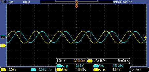
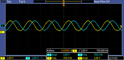
The above figure is @152Hz, the input (channel 2)centered in 2.5V has a
amplitude of 1.5V. We can see the peak-to-peak value of Vout is about
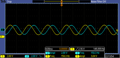
3V, which means input and output have the same peak value and the output is leading input T/4. The phase shift is +90 degree.
By increasing the input frequency, the peak-peak value of output is decreasing. From the 60Hz to 220Hz, the output value reduces from 5.28V to 2.16V. This simulation proves the hand calculation equation: |Vout/Vin|=1/2pi*f*RC.


4. Discuss the phase shift between the input and the output. Neglecting the R2 or remove the R2, the phase shift is determined by tan-1(2pi*f*R1*C). If we consider the R2, the phase will be determined by tan-1(2pi*f*R2*C). That means the phase decreasing slope is different by increasing input frequency. R2 makes the slope sharper.
That is what depicted in these results.
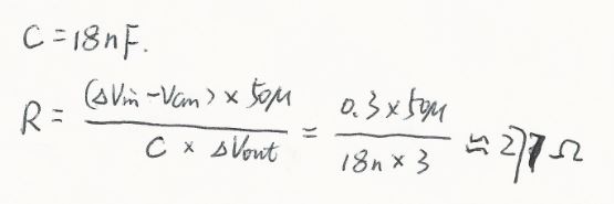
5. Next, the following circuit is used to generate a triangle wave output from a square-wave input. The input and output frequency is 10kHz. And the output ramp swings from 1 to 4V centered on 2.5V. First, we set the capacitor with 18nF. From the video, we know that dV=1/C*amplitude of Vin/R*T/2. If the input amplitude is 1.5V from 1 to 4V, VCM=2.5V, the R is equal to 277ohms (In this experiment, 270ohms is used).
Follow above considerations, we build up the following circuit.
The LTspice simulation result is shown below.


The experimental result is shown below.

Summary:
From above experiments, we study use the opamp to build up the integrator. And we know how to consider the trade-off between the capacitor, resistor and input/output amplitude and frequency.