Lab 7 - EE 420L
Authored
by Worku, Yetneberk
E-mail: workuy@unlv.nevada.edu
Today's
date 04/28/14
Pre-lab work
A. This lab will review the datasheet of the ZVN3306A and ZVP3306A MOSFETs.
Push-Pull opamp
Lab description
A. Review Push-Pull amplifier Characterized in lab 6
B. Design an audio amplifier (frequency range from roughly 100 Hz to 20 kHz) by using many resistors, ZVN3306A transistors, and
ZVP3306A transistors. Also, can be use only one 10 uF capacitor
and one 100 uF capacitor. The supply voltage is 5V, and the output is connected to an 8-ohm speaker (so, ideally, the
output resistance of your amplifier is less than 1 ohm).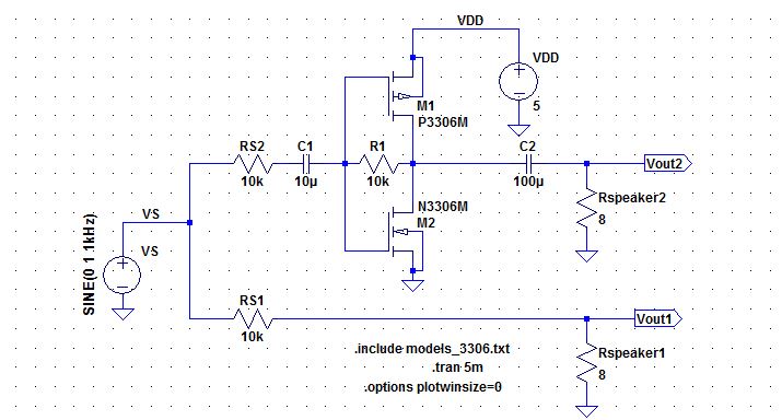
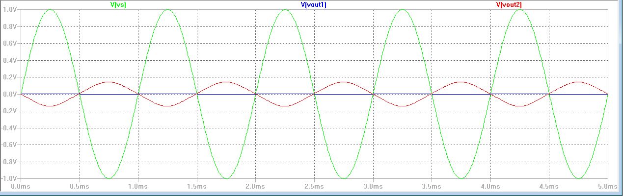
The experimental result is shown below
1.
To design audio opamp, the output is connected to an 8-ohm
speaker; therefore, we can use big capacitor to seperate the RL and the
Ro, also that make Rout smaller. however, to replace source singal can
be using sinewave 1V @1kHzwith 10kohms, by doing this Gate node the
input resistance is 1/gmn || 1/gmp. Indeed, by using push-pull
amplifier, the ouput signal is higher to drive3 8-ohms load.
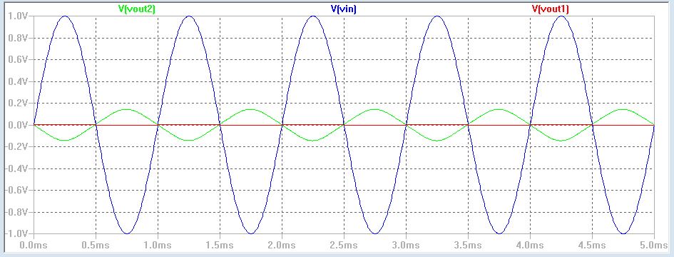
2. Below, the LT spice model can show the results.
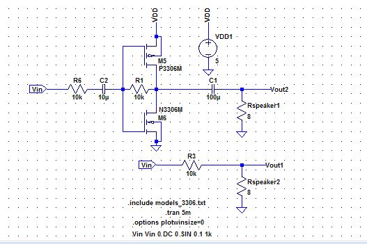
3. when VDD = 10V the output signal is not stable because of noise or other, therefore we replace it with 5V.
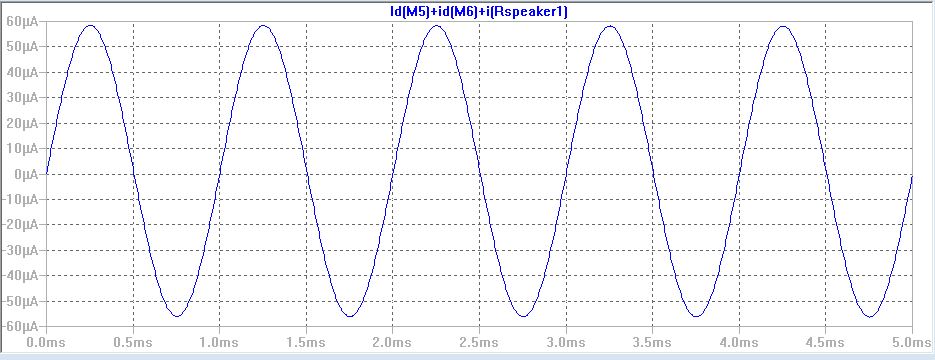
4.
Power dissipation opamp is adding up PMOS, NMOS, and load resistor1 of
power. The following LTspice simulation show result, and power
dissipation is 5V*60uA=300uW. However, can not find from datasheet Id
current, when VDD is 5V.

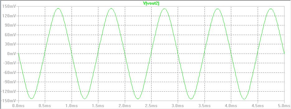
output swing
The output swing for the designed push-pull opam is+/-140mV

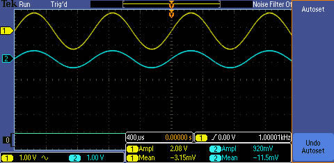
input resistance
current through 10k resistor is (1-Vg)/10k = (1-460mV)/10k = 54uA.
Rin = 460mV/54uA = 8.1kohms
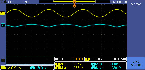
output resistance (Rout)
calculating Rout on output node, treating the opamp as voltage with a serial resistor byThevenin's theorem. So we can get
(Vout1-V)/iout1=Ro
and (Vout2-V)/iout2=Ro. Thus the Vout1-iout1*Ro=Vout2-iout2*Ro. Based
on the experimental result, I get Vout1=147mV, iout1=18.5mA.
Vout2=207mV, iout2=25mA.
Indeed, the expected result have some slide different from lab experiments, however we studies how to design an audio apamp.
Add
a return to the listing of your labs
Return to the listing of my labs
Return to the whole class reports
Return to the EE421L
Return to the CMOSedu.com