Lab 5 - EE 420L
Authored
by Worku, Yetneberk
E-mail: workuy@unlv.nevada.edu
Today's
date 03/31/14
Op-amps III, the op-amp integrator
Pre-lab work
A. Wach the video op_ampsIII, and simulate the circuits.
B. Read the write-up provided on the lab website.
Lab Description and Goals:
1. Calculate the frequency response of the circuit, and verify calculations with experimental results
2. Show, at the unity-gain frequency of the integrator, that the input and the output have the same peak values.
3. Build, a square-wave to triangle wave generator with frequency.
Lab five
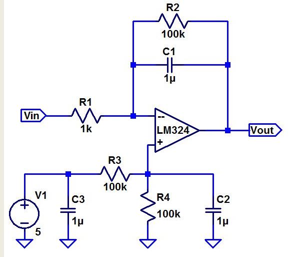
1.
Calculate frequency response the obove circuit. However, when R2 is
very lage, the voltage divider will be ignored because R1/R2 it goes to
zero, so that the following hand calculation will prove it.
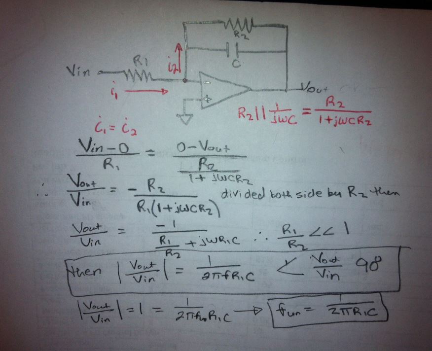
Hand calculation of the unity gain frequency of the circuit is 159.24Hz
Fun = 1/(2*pi*1000*0.000001) = 159.24Hz
Now LT spice simulation showing below.
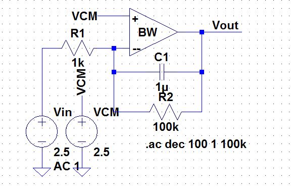
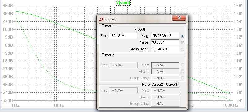
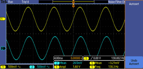
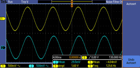
Build the circuit in lab, the results as follows
The
experimental results are showing that the input and the output
waveforms have an equal peak value that means R2 value doesn't affect
the experimental result; showing the image below
Square-wave to Triangle-wave Generator
A. design, simulate, and build a square-wave to triangle-wave generation cicuit.
B. The input/output frequency is 10kHz and the output ramp must wing form 1 to 4V centered around 2.5V.
C. Show all calculations.
we
set the capacitor with 18nF. We know that dV=1/C*amplitude of
Vin/R*T/2. If the input amplitude is 1.5V from 1 to 4V, VCM=2.5V, the R
is equal to 277ohms
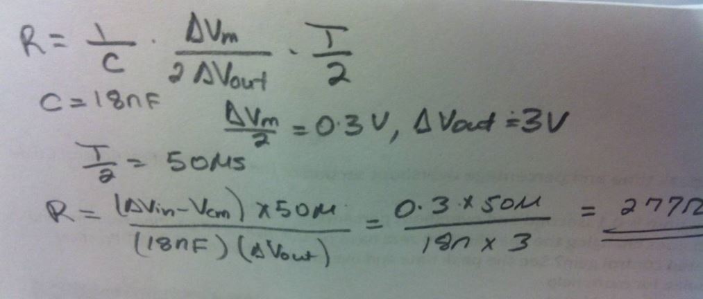
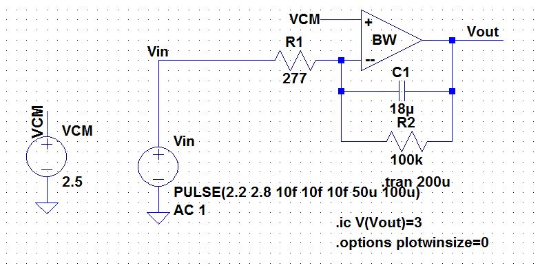
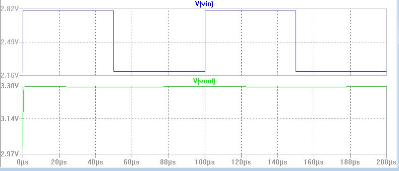
according to the above calculation the LTspice simulation result is shown below, but I could not get triangular form on V(out).
The experimental result is shown below
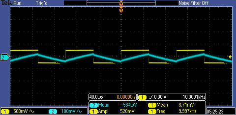
Indeed, the expected result have some slide different from lab experiments, however we studies how to buid up the integrator.
Add
a return to the listing of your labs
Return to the listing of my labs
Return to the whole class reports
Return to the EE421L
Return to the CMOSedu.com


