Lab
X - ECE 421L
Authored
by Worku, Yetneberk
E-mail: workuy@unlv.nevada.edu
Today's
date 02/08/14
Lab
description and Discussions of Scope probe
A. Scope
waveforms of 10:1 probe are undercomensated, overcompensated, and
compensated; showing consequently as the following.
1. showing on LTspice simulation of a 10:1 scope probe with no scope
a. using hand calculations
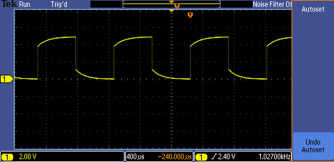
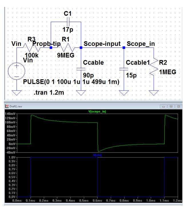
2. showing LTspice of a simulation of 10:1 probe with overcompansated
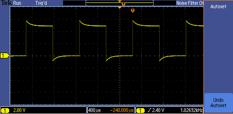
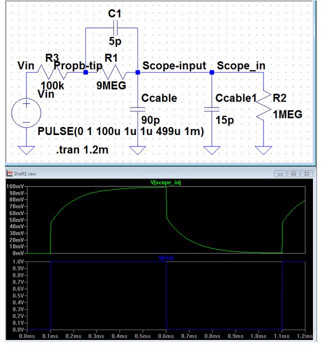
3. showing LTspice simulation of a 10:1 probe with undercompansated
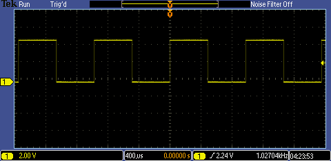
4. showing LTspice simulation of a 10:1 probe with compansated
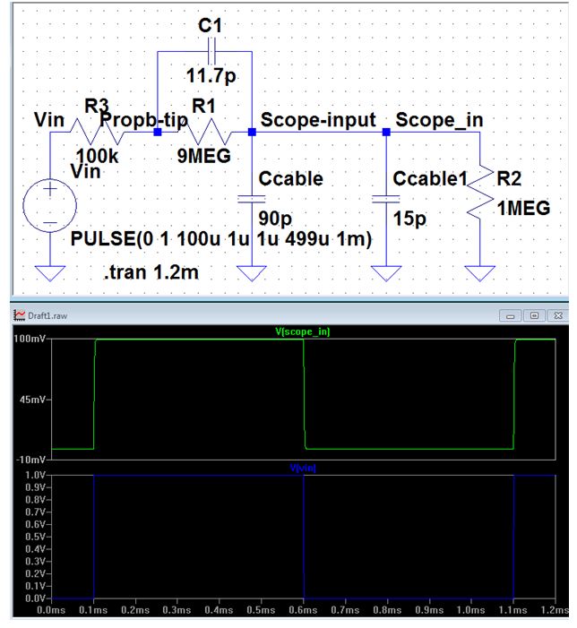
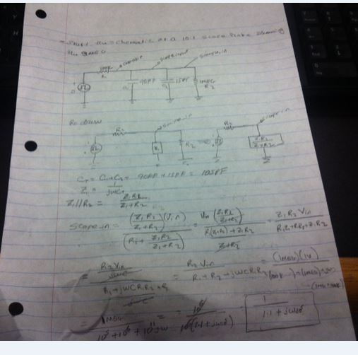
B. This is the draft schematic of a 10:1 scope probe
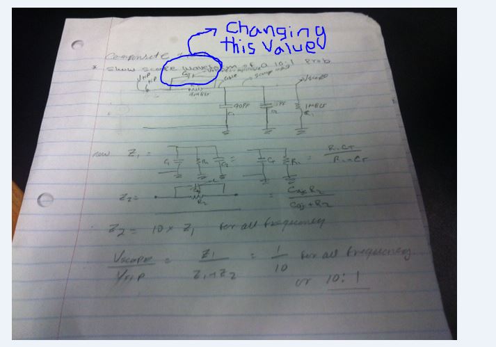
C.
Finally, compansated, undercompansted, or overcompansted will happen
by changing the Capacitance values, or by switching the probe tip
has switch, for example need to set the scope input to be 0.1 of the
test point, then turn to 10x side. Also, use circuit analysis and make
some assumptions; the hand calculations show as
follows.
Experiments by using Comensated scope probe
1.
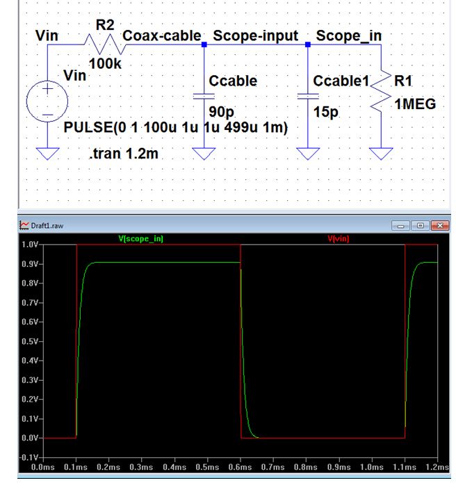
The first experiments using a scope, pulse generator, and a resistor to
measure the capacitance of a length of cable. using the figure below,
can get input and output of transient result, then measure the td(time
delay). td=0.7RC, so C=td/0.7R
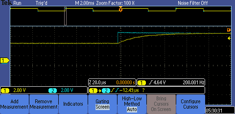
C=(-12.9us)/(0.7)*(100k)=180*10^-12F
however, we can use the capacitance meter to measure the cable capacitance for comparing with the simulation result.
Indeed,
we can connect the cable to implement a test point on a PCB board after
adding a resistor and capacitor in parallel.
Add
a return to the listing of your labs
Return to the listing of my labs
Return to the whole class reports
Return to the EE421L
Return to the CMOSedu.com