Lab 1 - EE 420L
Authored by: Roman Gabriele Ocampo
Email: ocampor5@unlv.nevada.edu
Date: February 5, 2014
Review of basic RC circuits
Prelab:
- Obtain a CMOSedu account
- Review how to edit webpages
- Read the lab write-up provided on the lab website
Lab Description and Goals:
The
goal of this lab is to simulate, and verify the results, the circuits
in Figures 1.21, 1.22, and 1.24 in the book. The following is required
for each figure:
- Circuit schematic showing values and simulation parameters
- Hand calculations
- Simulation results verifying hand calculations
- Scope waveforms verifying both simulation results and hand calculations
- Disscussion of the results
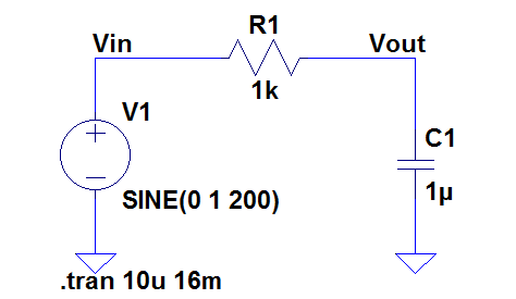
Figure 1.21
Hand Calculations:
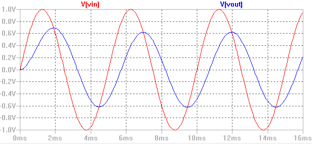
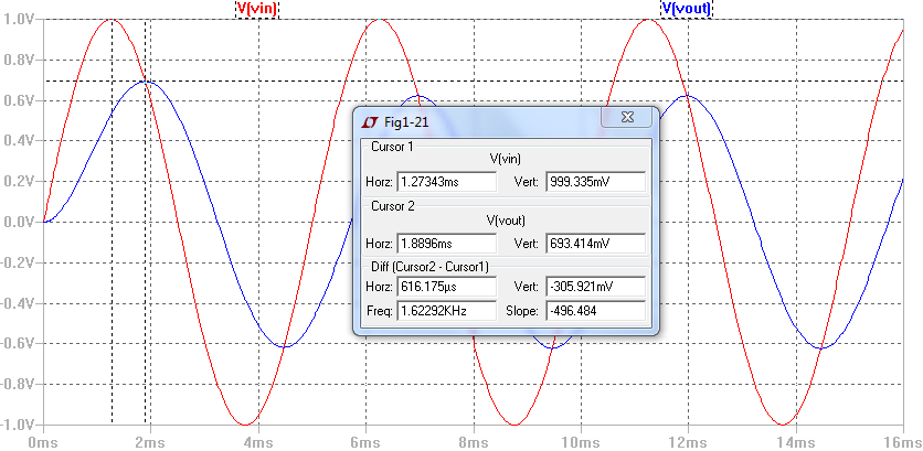
Sim Results:
Vin
is set at 1V and Vout was calculated to be 623mV. The sim results show
a Vout of 693mV. The time delay was calculated to be 715µs and the sim results indicate a time delay of 616µs.
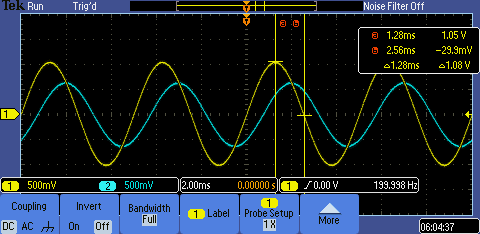
Scope Waveforms:
The measured waveforms indicate a Vout of 640mV and a time delay of (2.00-1.28)ms = 720µs.
Variation of parameters and discussion:
From
the hand calculations above, one can see that the output amplitude is
inversely related to the values of R and C. As such, one would expect
that as R or C is increased, the value of Vout would decrease. On the
other hand, the phase is directly related, thus an increase in R or C
would increase the time delay. The simulations below show the effect of
increasing R and C values:
R-Varied:
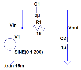
C-Varied:Figure 1.22
Hand Calculations:
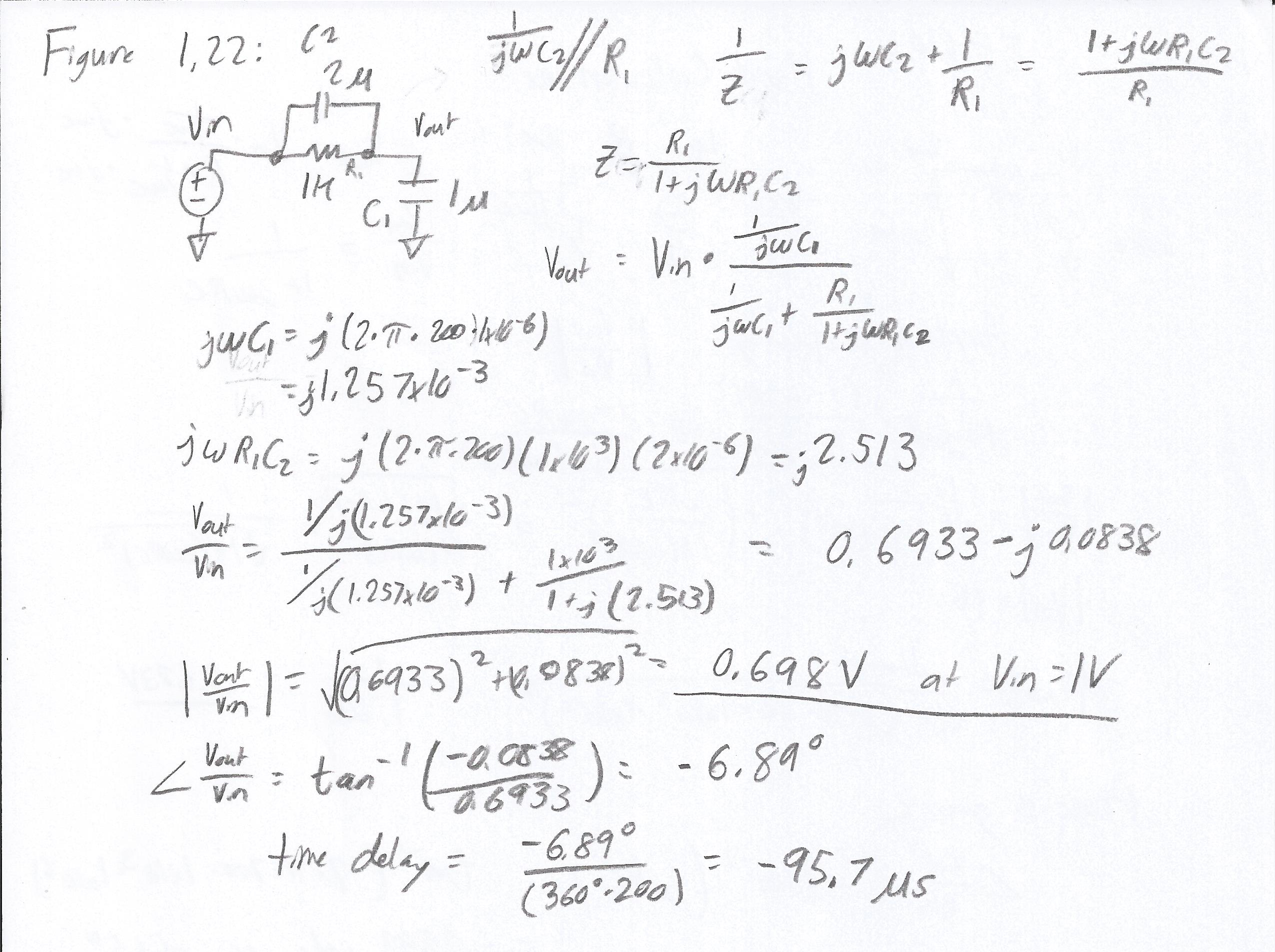
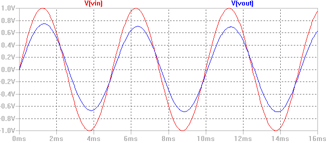
Sim Results:
Vin is set at 1V and Vout was calculated to be 698mV. The sim results
show a Vout of 746mV. The time delay was calculated to be 95.7µs and the sim results indicate a time delay of 83.0µs.
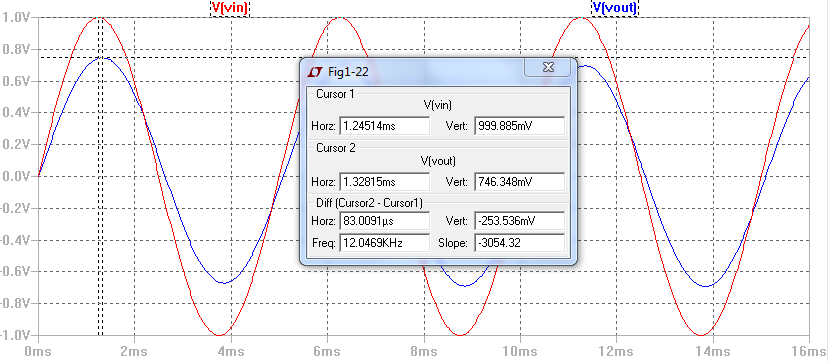
Scope Waveforms:
The measured waveforms indicate an output voltage of 740mV and a time delay of (1.40-1.28)ms = 120µs.
Figure 1.24
Hand Calculations:
Sim Results:
From
the hand calculations above, the peak output voltage should measure
950mV after the capacitor has been charged for 3ns. The simulation
results indicate a peak output voltage of 957mV.
Scope Waveforms:
Unfortunately,
we cannot recreate the circuit in Figure 1.24 with the materials and
equipment present in the lab. This scope waveform was generated using a
1µF capacitor and a pulse input signal at 100Hz and 33% duty.
Return to the listing of my labs
Return to the whole class reports
Return to the EE420L site
Return to CMOSedu.com