Verilog-AMS
Tutorials using SMASH from CMOSedu.com (Return)
Tutorial
2 – Performing transient simulations
For this tutorial
we will modify the basic circuit we built in tutorial 1 and make it
into an RC
circuit. Then we
will perform a
transient analysis on the circuit to see the RC delay.
1. First let’s create an
RC circuit using the
steps we learned in tutorial 1.
2. Create a new circuit
file and name it basic_sim2
3. Open the existing basic_sim_top.va file (FileàOpen...; change
the file type to Verilog source
files. This will
make it easier to find)
4. Instead of creating a
new top file we will
simply add a new module to the existing one.
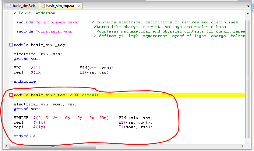
5. Create a new module
and name it basic_sim2_top
6. In this new module we
need 3 components: a
pulse voltage source, a resistor, and a capacitor.
If you follow the circuit schematic of Figure
1.24, you will get an idea of how to setup your RC circuit.
7. You will need three
nodes this time: vin,
vout, vss. Connect
the vpulse source to
vin and vss. Connect the resistor between vin and vout, and connect the
capacitor between vout and vss.
8. For
the voltage pulse source to work, we need to feed it the proper
parameters. For
this demo enter the
following set of numbers in this order:
#
(0, 5, 2n, 10p, 10p, 10n, 20n). This
data string of data basically sets the parameters of the source. Based on these numbers the
source is set to
pulse from 0 to 5 volts, with a time delay of 2ns, with a rise and fall
time of
10p, with a pulse width of 10ns and a 20ns period.
Remember, if you are never sure what order to
pass parameters in always refers to the component library that holds
the module
for it.
9. Once you have
completed the new module save
the file and close it.
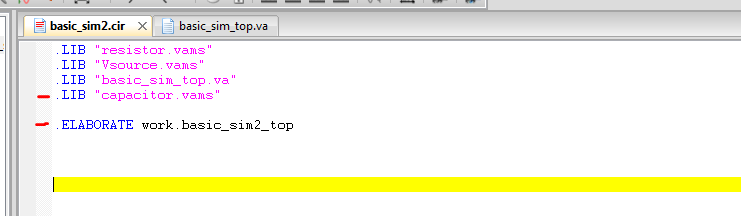
10. Now open the new
circuit files (basic_sim2)
and add your component libraries and top file to it.
11. Compile your circuit
file (remember we do
this by saving it, closing it, and opening up again) to make sure it
has no
errors. If
successful you are now ready
to perform a transient analysis on the circuit.
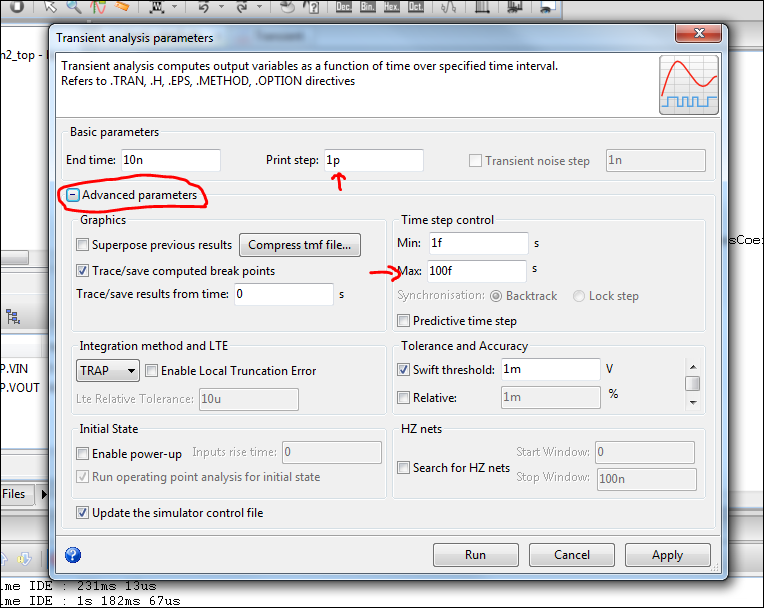
12. To perform a transient
analysis select AnalysisàTransientàParameters...
13. The menu will open up
and you can select
your end time and step size of your simulation.
Pressing the Run button will instantly perform the
simulation. Pressing
the Apply button will save the
parameters settings you have selected and place them in the circuit
file. Lets select
APPLY first.
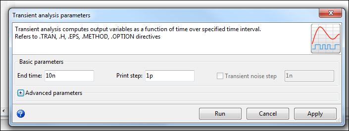
14. After selecting Apply
you will see the spice
commands that perform a transient analysis.
This is useful since SMASH does support command line spice
(i.e. you can
just type what you want here and have it execute).
The best suggestion is to use the menu to
perform simulation and edit the spice commands later for faster changes. Now let’s go back to the
transient menu and
select Run this time.
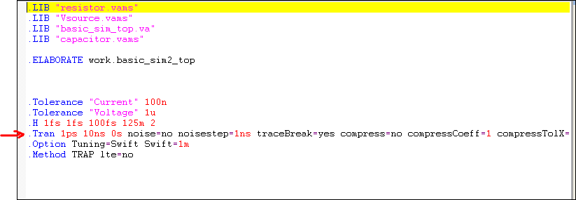
IMPORTANT!:
when selecting your step size
(print step parameter) you must make sure that it is not greater than
or equal
to the max Time step control. The
Time
step control acts as an override meaning if you wanted to use 1n for
the steps
and the time control list 1m as the max, your simulation would default
to
1ms. To change this
open the advanced
parameters section to change these settings.
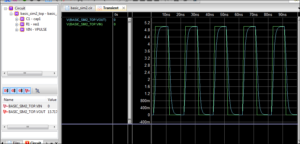
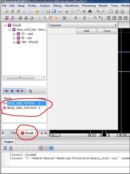
15. A simulation window
will open and you will
be prompted to add which signals you want to simulate. These signals are located on the left panel
in two areas. The above (purple) names will give you the current that
flows
through those components. The
below
(ones with signals next to their name) provide voltage of the given
names. These names
generally match the node names
that were placed in the top file. To
add them select the node you desire and press the add button. If successful you will see
a line popup in
the background. This
signifies a new
graph for the new signal. When
you are
finished adding signals press the close button.
16. After closing the
previous menu your
simulation should begin immediately. If
it is complex you will see a green status bar on the bottom right of
the screen
signifying the progress of the simulation. Once it is complete your signals will appear on the screen
in their
respective graphs
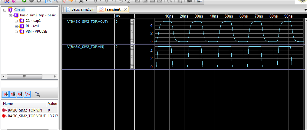
17. Now that your
simulation is done you can
modify you graph by adding more signals or by combining multiple
signals onto
the same graph. To
add signals select
ProbesàTrace Nets And Signals... Once you add more signals
you will need to
run the simulator again (press the play button or go to DebugàGo).
18. To combine signals
grab the signal name
with your mouse, drag and drop it into the graph you wish to combine it
with.