Verilog-AMS
Tutorials using SMASH from CMOSedu.com (Return)
Tutorial
1 - Creation and setup of a basic circuit file.
1. Create a folder named
“Tutorials” on the desktop.
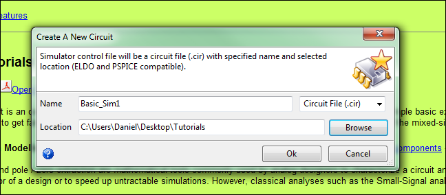
2. Next, "Create A New Circuit" using the menu items FileàNew Circuit...
3. A window will open. Select Circuit
File (.cir) from the drop down menu as seen below.
Name the project "Basic_Sim1" and then select the Tutorials
folder created in Step 1 for the location of the circuit file.
4. The next window to
open will be the circuit
file. This file
will contain the main
headers of all the component files you use as well as the top level of
the
circuit you build. This
file will also
have the spice commands of the simulations you perform.
To get started lets add some basic header
files.
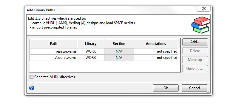
5. To add your library
(aka header) files go
to menu items SetupàLibrary Paths...
6. Click the Add... button
and add the
Verilog-AMS (.vams)
files you wish to use, and then
click Ok. (For this
demo I save several
component files in the folder so adding them to project would be easy)
7. If you are successful
you will see .LIB
followed by the name of the files you added. The next step is to build
a
circuit. You can
accomplish this in two
ways. You can
create a spice netlist in the
current file and use the .LIB as references or you can create a
separate file
and “build” the circuit there. For
this
tutorial we will do option 2 since it is the option you will use the
majority
of the time
8. Select FILEàNEW to open a blank
document. From here
you will build a circuit based on the
library of components you added.
9. First you must include
two more .vams files. Type:
`include “disciplines.vams”
and `include “constants.vams” These
two include files various
constants used when writing Verilog-AMS such as PI and electric charge.
10. Next you need to
create a “module.” This
module is essentially a block where you
will build your circuit. Just
as you
would in a GUI based simulator you must define the parameters of your
block. First name
your module in the
following syntax: module {module_name};
An example would be module basic_sim1_top;
11. After you named your
module you need to
define the nodes of the system. The
next
line you text should be: electrical
{input/output parameter};
an example would be: electrical vin,
vss;
where vin
and vss are nodes of
the module. (NOTE:
typing electrical is crucial since it
allows the nodes to behave with electrical characteristics. If you neglect typing
electrical then the nodes
will create errors and not behave properly during simulation.)
12. Next we should define
our ground (if one
exists.) In this
tutorial I will treate vss as ground so I must
also type: ground
vss; this
makes ground the reference points for all electrical simulations later
on. This is almost
always required since there is
some ground within any circuitry.
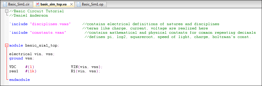
13. Now we should define
our components. The
syntax for define a component is: ) {Verilog_source_name}#(parameters) component_name(
passed nodes). For
example, in this
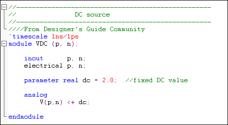
tutorial I wish to define my voltage source I would type: VDC #(1) VIN(vin, vss);
If
I were to check my “Vsource.vams”
file I would see
the names of various sources.
Based on the Vsource code I see that the VDC source has two parameters (p,n) so to use this component I must pass two parameters when I call it (vin, vss). There is also a single parameter (dc = 2.0). Therefore I need to pass a single value to represent the dc source value (#(1) means I pass 1 to the dc parameter). If I neglected to pass a parameter then the default value would be used (2.0). Notice that the name VDC is used in the Vsource code and in our top module are the same.
14. I now wish to create a
resistor so I will
do the same steps I performed to create a voltage source: res1
#(1k) R1(vin, vss);
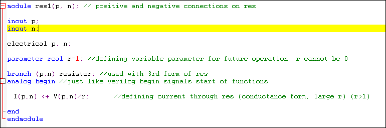
You may notice
that both components share the same nodes.
This means they are electrically connected together. In this case my source is
in series with my
resistor.
15. Once you are finished
adding all of your
components, you need to “close” the module by typing: endmodule.
16. Once completed now you
need to save your
module. Select FILEàSAVE
AS and save the file as a .va
file (verilog-A)
17. Now lets
go back to our circuit file. From
here
we can now add our module file to the circuit files so we can perform
simulations. Just
like before we add
module file the same way we added the .LIB files
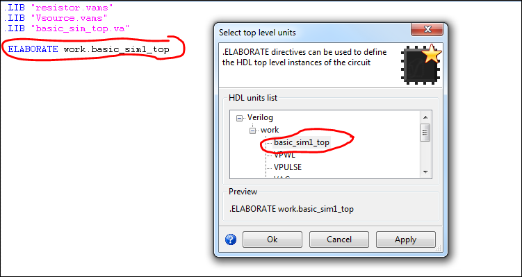
18. Once you have added
the module go to SETUPàTOP
LEVEL INSTANCES.
A new window will open.
Scroll down until you find the name you’re
your module (not the name of the file but the name you placed after the
word
“module”.) NOTE:
sometimes the module
name is not present. This
means you need
to reload your circuit file. Save
the
circuit file, close the circuit file, open the circuit file again, and
a dialog
box should open prompting you to select the top level instance. (if will be under the work
expansion)
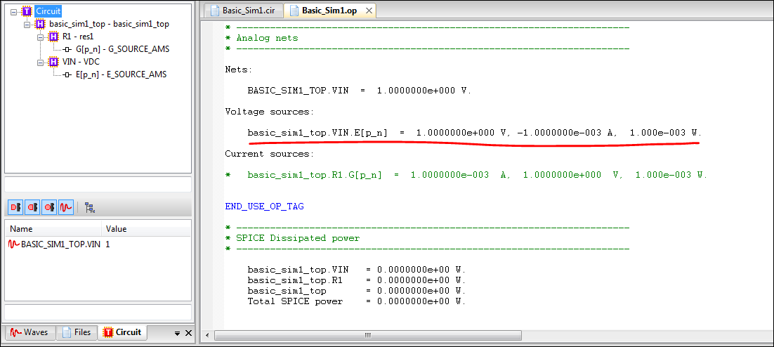
19. Your circuit is now
complete. To verify
its operation you can run an .op (ANALSYSàOPERATING
POINTàRUN) to check if the
current and voltage
levels match as expected. In the case of this tutorial we would expect
that a
1V source in series with a 1k resistor would generate 1mA of current
and 1mW of
power.