HSPICE
from Synopsys
can be
used to simulate the circuits from the CMOS
books.
- Download the book’s available HSPICE
simulation examples in HSPICE_CMOSedu.zip.
- To
ensure that HSPICE generates a data file for Avanwaves
or Cscope add “.option post” to a netlist
- HSPICE netlists end in an “sp” (e.g. mynetlist.sp)
- HSPICE uses Level=49
for BSIM3 and Level=54 for BSIM4
- Syntax
for a switch in HSPICE is:
GS1
n1 n2 VCR
PWL(1)
CLOCK,0
0.499,1m
0.501,10G
For
example, if the voltage difference between nodes CLOCK and ground (0)
transitions through 0.5V the switch, connected between nodes n1 and n2,
will go
from a short (1 milliohm) to an open (10 Gigaohms).
The Electric
VLSI Design
Information
- Below
shows how Electric is setup where the Run Program path is (for
example): C:\synopsys\Hspice_A-2008.03-SP1\BIN\hspice.exe
- Note
that while the Run Program field is not case sensitive the “with args:” field is case sensitive (so use the
uppercase names
as seen)
- Also
note the difference between the “with args:”
field
seen below and what is used with LTspice
- Electric
outputs netlists with a *.spi extension.
- If you
get an Exception Caught! when Electric loads simulation data it likely
means
that you have run out of memory. See number 15 here
for how
to increase the memory allocated to the JVM

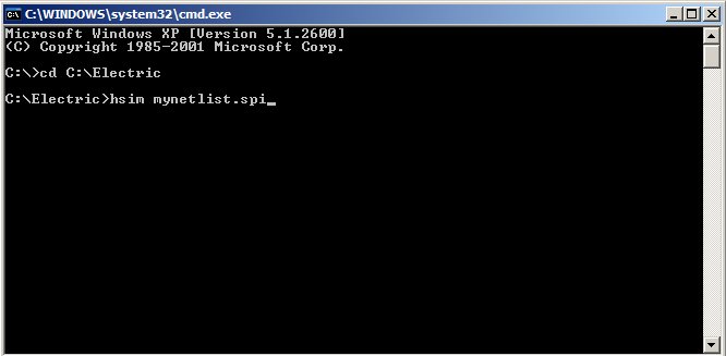
Running
HSIM
from the command window (Start -> Run -> then type Cmd)
in Windows
- Ensure
the HSPICE model levels are used as indicated above (e.g., BSIM3 is
Level=49
instead of Level=8)
- Use
exact same netlist as used with HSPICE
simulations
except replace .options post with .print v(*) Level=1
- .print
v(*) Level=1 saves node voltages from the main, or top level, cell.
Level=2
stores node voltages from both the top level cell and the cells
directly
instanced in the top level cell (Level=3 stores the top three levels of
hierarchy, ect.)
- HSIM
can be run from the command prompt as seen below
- The
errors can be viewed using a text editor in hsim.log
- The
simulation output, hsim.fsdb, can be
viewed using CosmosScope
- See the
HSIM manual covering invoking HSIM for additional options
- If you
get an Exception Caught! when Electric loads simulation data it likely
means
that you have run out of memory. See number 15 here
for how
to increase the memory allocated to the JVM
Return to:
CMOS Circuit Design, Layout,
and
Simulation
CMOS Mixed-Signal Circuit
Design