On
page 625 you state that a system
with positive feedback can be stable if its closed-loop gain is less
than one.
How do I simulate the loop gain of
the
BMR in Fig. 20.15 to see that it’s
less than one?
One
way to simulate the loop gain, vf /vin
or AOLβ,
is seen below (click for a larger image). The inductor is a short for
DC but
blocks the AC input
signal.
Note the use of a huge
capacitor and inductor (we can do this in a simulation ;-). For DC
purposes
this schematic is exactly the same as the
one
seen in Fig. 20.15. See additional
comments at the bottom of the page.
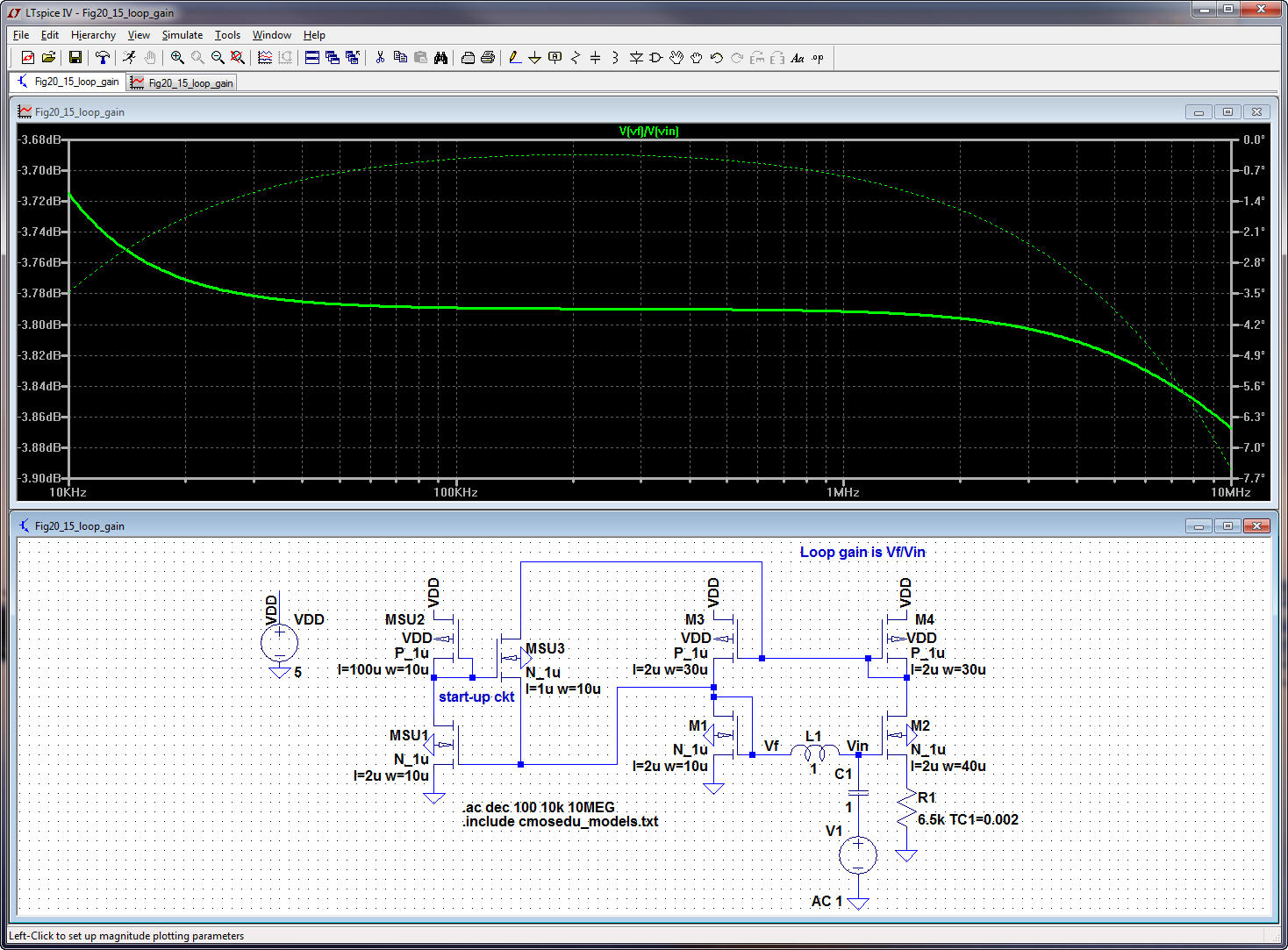
Note
that, as mentioned on page 625,
it’s easy to increase the loop gain by increasing the capacitance on
M2’s
source to ground (this is bad!, see below).
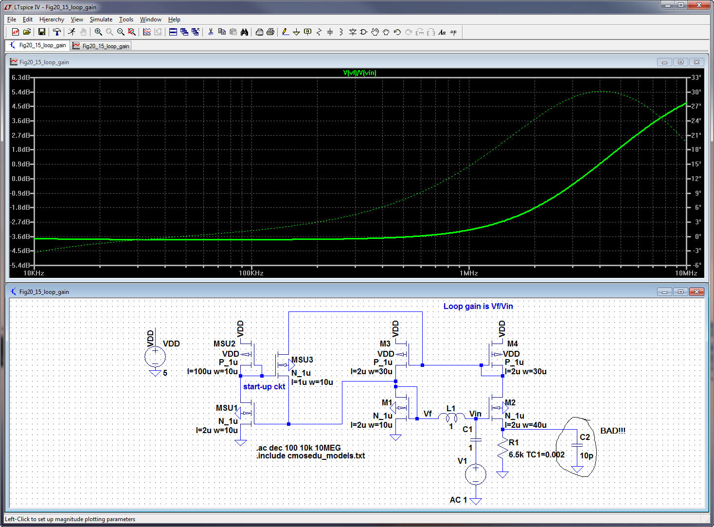
A few
more comments (for the analog
gurus ;-), there are many ways to look at this circuit. Here is one.
The output
is the drain voltage of M2, vd2.
Since the
VSG
of M4 is set by this output voltage we could also say that the output
is the
drain current of M4 or M2. The open circuit gain, AOL,
is vd2/vin
which is
(1/gm4)/(R1
+ 1/gm2)
noting
that this is less than one. Also note that gm3
= gm4
and gm2
= Kgm1
where, above,
K is 4. The feedback voltage, vf,
is
connected
directly
to the input (no external
source, that is, it’s self-biased) and given by gm4vd2/gm1.
So we can
write β = gm4/gm1
which is often
close to one. The loop
gain
is βAOL
which is simply AOL
(the
open-loop gain) when β = 1
(which
is the case above). Since the circuit employs positive feedback we can
write
the
closed-loop
gain as ACL
= AOL/(1 – AOLβ).
So, as can be seen here, if AOLβ
is greater than or equal to one the circuit becomes unstable. A good
design
will
ensure
that the loop gain, AOLβ,
is well below one.
Again,
repeating the above information,
we can increase the loop gain by shunting R1 with a capacitor. This
drives the
impedance at the source of M2 towards
ground
with increasing frequency, this
is bad!
Note
that we are using an AC analysis
when discussing stability. A DC analysis is used to determine operating
point.
Also
note that it’s more correct, in
the last paragraph on page 625, to use “loop gain” instead of “closed loop gain”
since a loop gain, AOLβ,
of 0.6 will
result
in a closed loop gain, ACL,
of 1.5 (which obvious
isn’t less than 1 ;-). This typo is fixed in the third and later
printings of
the third edition.