Lab 3 - ECE 421L
Authored
by Ethan Yamamoto,
Email: yamame1@unlv.nevada.edu
9/19/23
Lab Description:
Layout of a 10-bit digital-to-analog converter (DAC)
LINK TO LAB3 ZIP
Prelab Description:
Prior to lab, backed up my work as seen in the image below.
I also finished Tutorial 1, as part of a previous HW so I just need to go back
and adjust our 8k resistors to 10K as shown below.
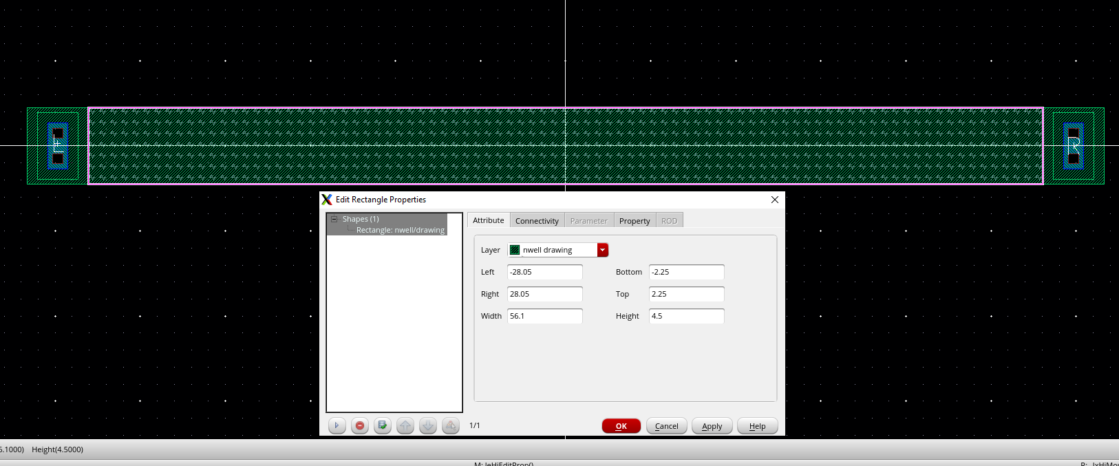
Showing 10k resistor
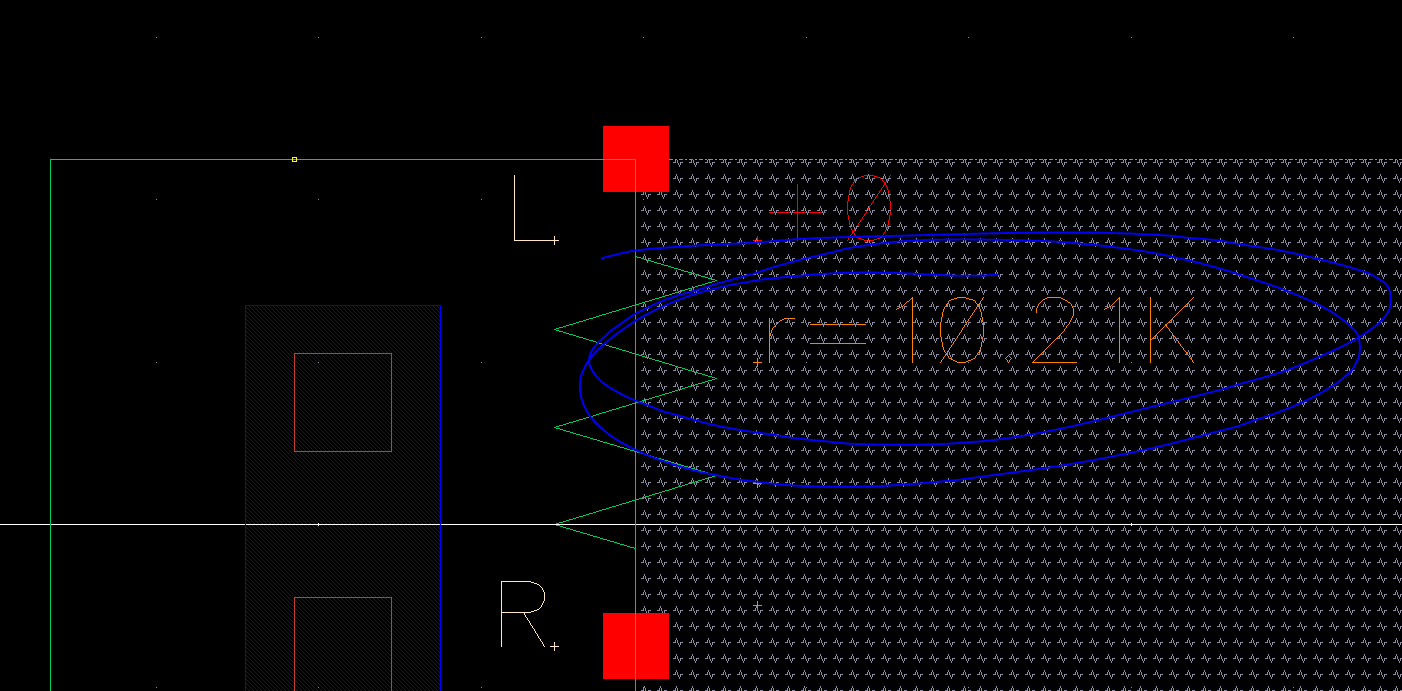
Showing extracred resistance is 10k ohm
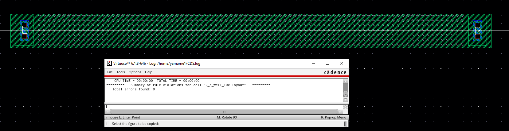
Showing clean DRC on 10k
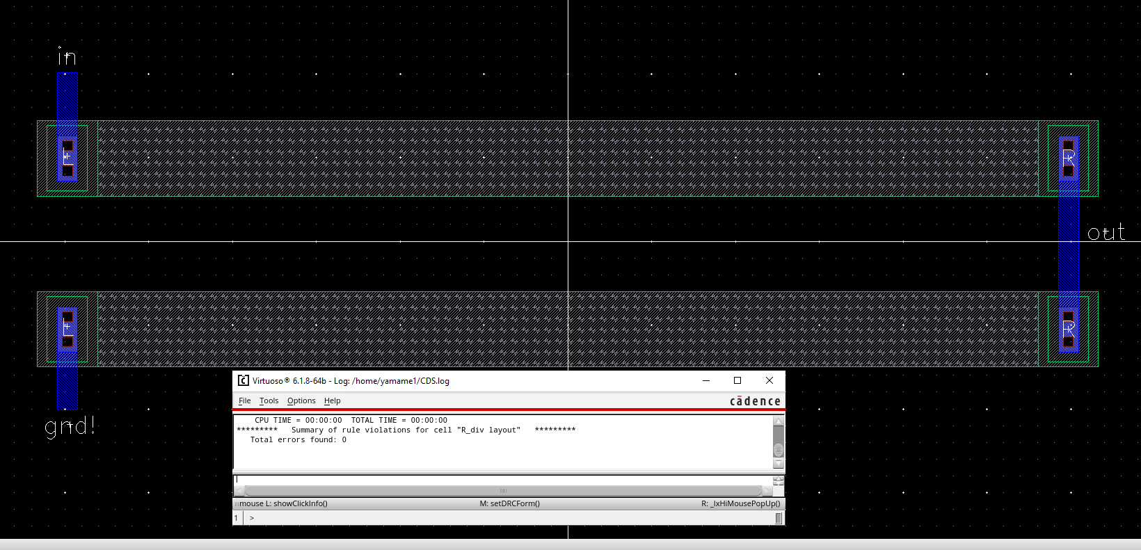
Resistors used in Voltage divider
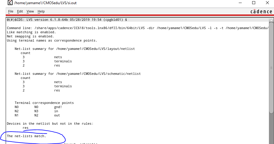
LVS of 10k voltage divider
Lab Results:
As shown in the prelab above I laid out a 10k resistor using the n-well.
We selected the width and length of the resistor by taking our
total resistance and sheet resistance into account.
We want 10k and have a Rs of 855. Our width just needs
to be greater than 3.6u on the C5 process. In the tutorial
they use 56um x 4.5um. If you solve R=Rs*(L/W) for L
using the above numbers you get ~52u but we need to adjust our values
to account for the connections which tend to drop resistance the more there are
hence 56um is used to get 10ohms.
We can measure the length and width in cadence by using the ruler or checking its properties.
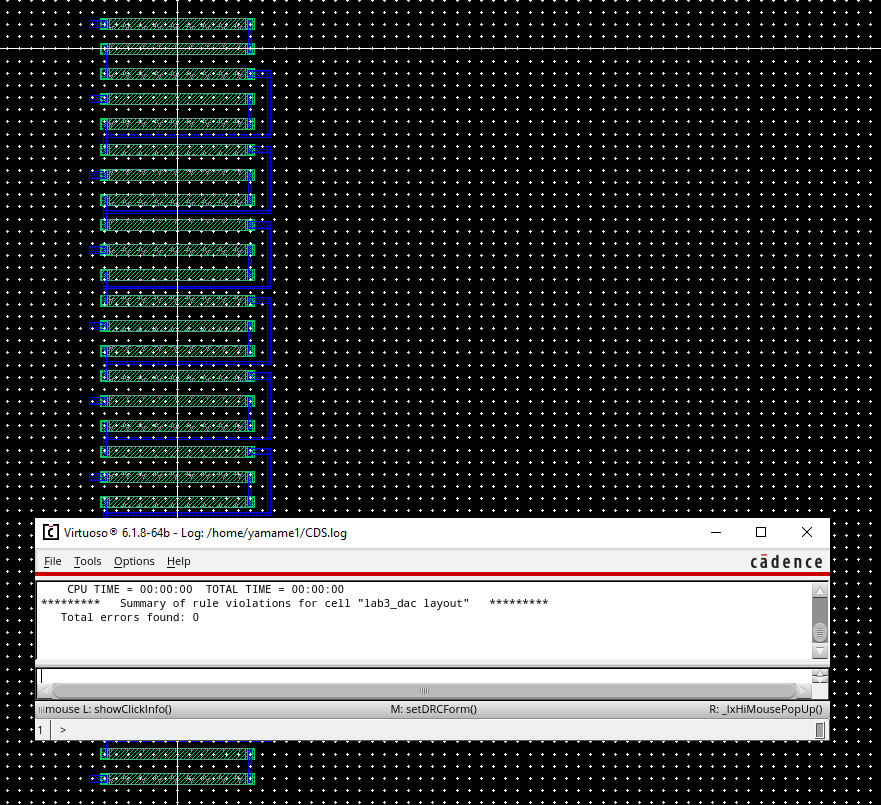
The above image shows my layout of the DAC with a clean DRC
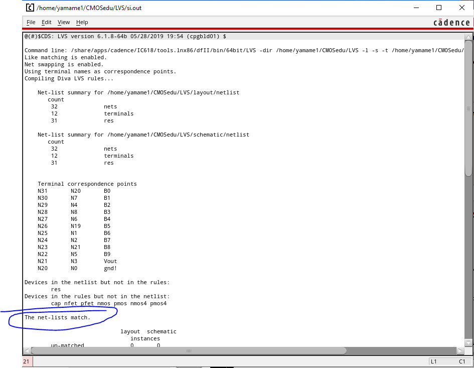
Clean LVS of layout made in this lab and DAC in last lab
Design directory Zipped and placed in lab3 directory linked on top of webpage
Work backed up as usual
Return to EE 421L Labs