Lab 3 - EE 421L
Authored
by Cody Woolf woolfc@unlv.nevada.edu
Today's
date: 13Sep2023
Pre-Lab:
Back-up: Zipped the entirety of my EE421 folder from my desktop and emailed it to myself.
Finish Tutorial 1: The following show the completion of Tutorial 1; starting from where Lab 1 ended.
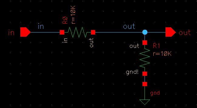
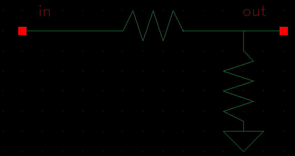
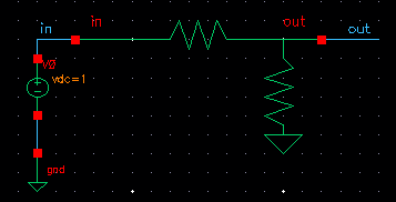
First, a voltage divider schematic and its symbol are created.
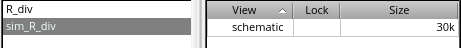
Next,
R_div was copied and named sim_R_div. From sim_R_div, the symbol was
deleted. This allows for use of the R_div symbol in building a
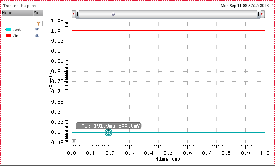
schematic in sim_R_div. Once the schematic was built, a simulation was
run to verify proper operation.
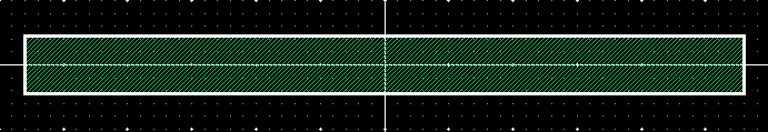
Following
the tutorial, a new cell view was created; layout. Here, a rectangle
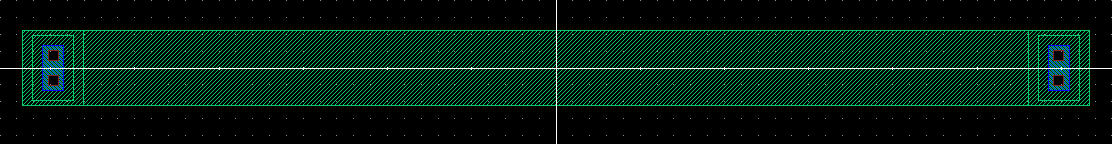
was drawn using the nwell. Once drawn, the rectangle properties were
modifed to have a length of 56.1 and a width of 4.5; ntaps were added
to each end of the rectangle. An overlapping rectangle was drawn over
the nwell rectangle to designate it as a resistor.
The layout is then extracted to verify that the correct resistance value was obtained.
The conclusion of Tutorial 1 is to make the voltage divider from the layout, do a DRC, and run LVS.
__________________________________________________________________________________________________________________________________________________
Lab
description:
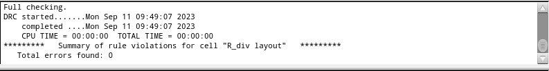
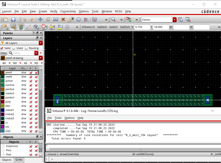
Displayed is a clean DRC of a 10k n-well; this was generated in the pre-lab.
In
order to determine the length and width of the resistor the following
formula is used: R = Rsquare*(L/W). Based on the tutorial, a width of
4.5um was chosen; therefore, 10kOhms = 855Ohms*(L/4.5um) which gives a
length of approximatley 56ums. To satisfy design rules a value
divisible by 1.5 should be chosen therefore the used length is 56.1um.
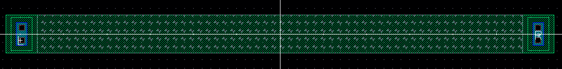
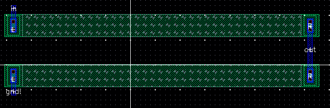
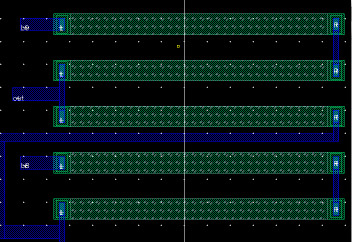
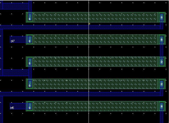
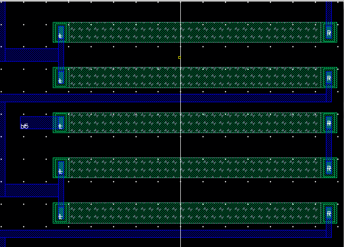
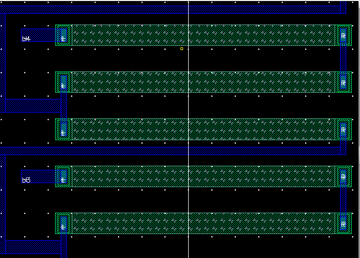
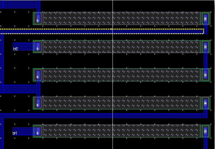
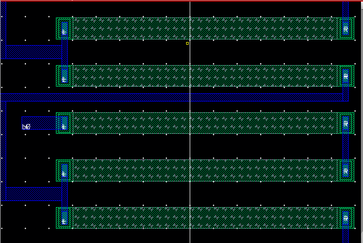
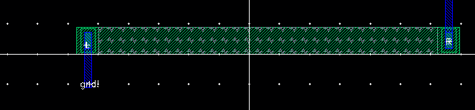
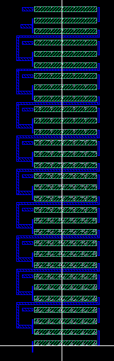
Below
is the 10bit DAC layout having the same x-position but varying
y-positions. The top is bit 9 going down to bit 0 with the last
resistor at the bottom being the load resistor. One n-well was placed
then copied; same as the metal1 wiring between bits.
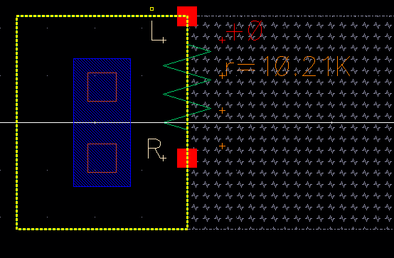
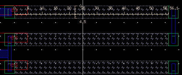
In
order to check that the length and width of the resistor are correct
use keybind 'k' to access the ruler. Below shows that the resistor
measurements match the length and width calculated above. Since the
first resistor was copied, all others are identical in measurement.
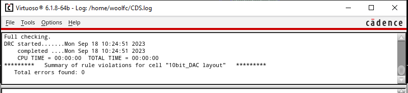
Next, the DRC is verified.
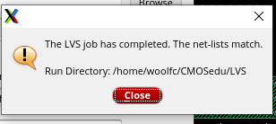
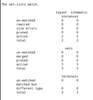
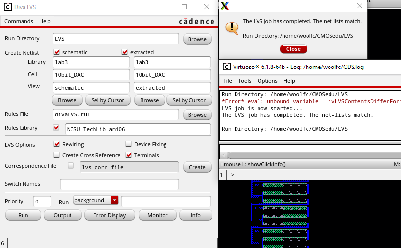
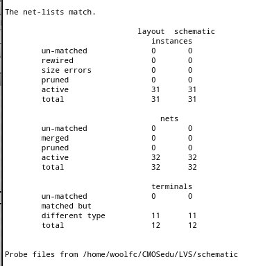
Last, the LVS is verified.
Click here for lab3.zip.
Return to Index