Lab 1 - EE 421L
Authored
by Cody Woolf woolfc@unlv.nevada.edu
Today's
date: 04Sep2023
Pre Lab:
The
prelab required reaching out to Dr. Baker to recieve a cmosedu.com
account, downloading and installing Kompozer, and download the lab
template.
__________________________________________________________________________________________________________________
Lab
description:
This
lab familiarizes us with using Cadence and Kompozer. This is
accomplished by running a simulation, generating the lab report, and
setting up the student webpage from which the lab reportwill be accessed.
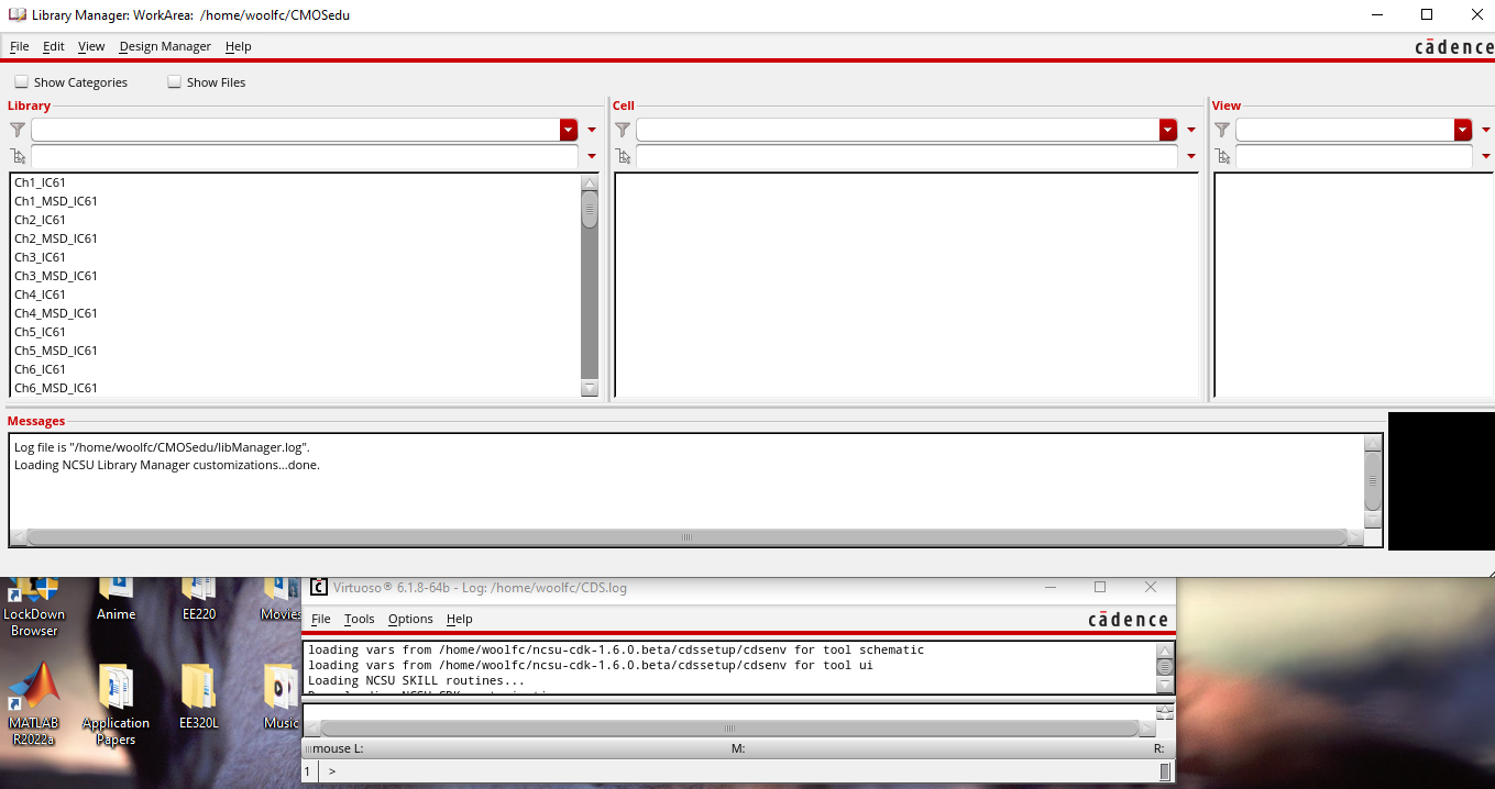
The first step was to launch Cadence by using the virtuoso & command in MobeXterm.
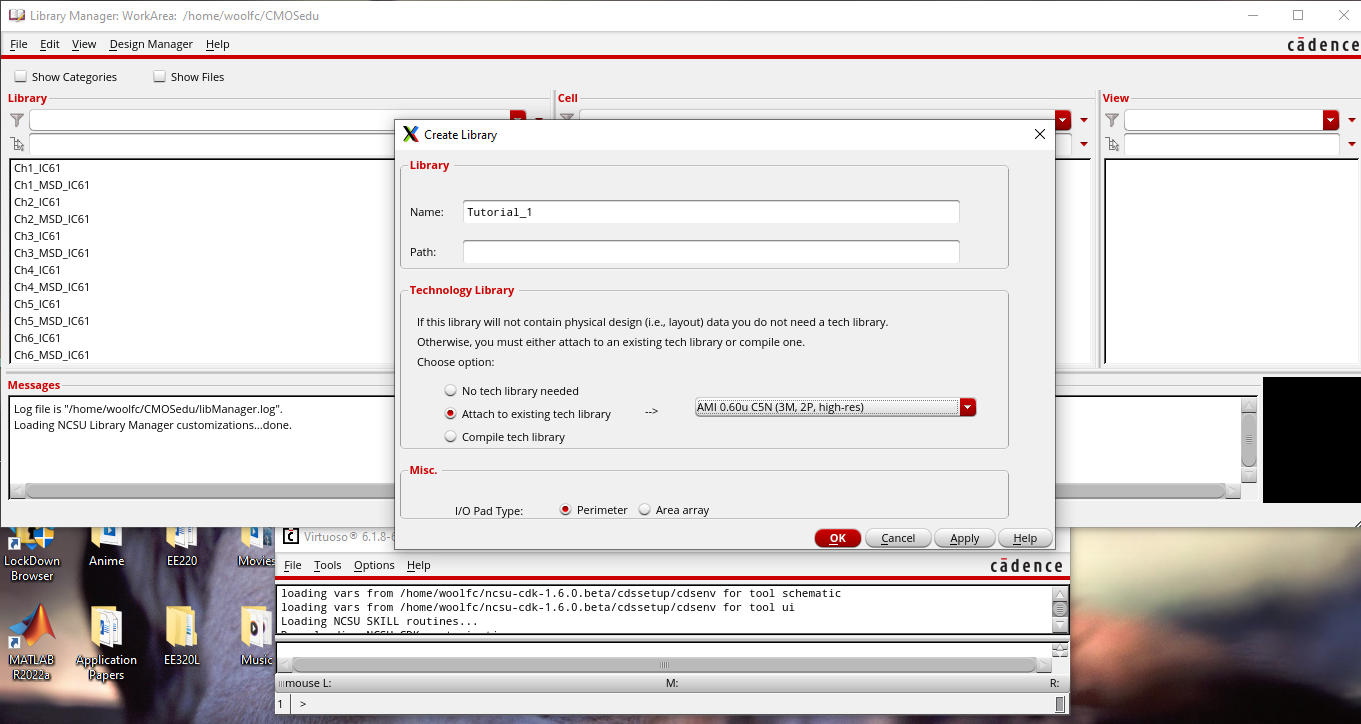
The second was establishing the appropriate library.
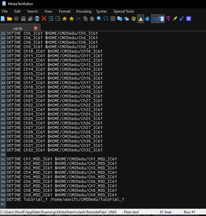
For step 3, it was verified that the new library was defined.
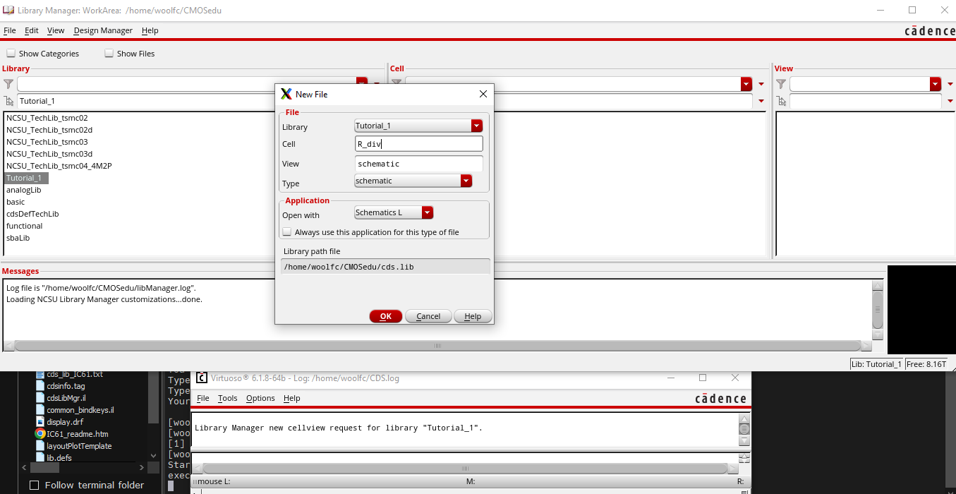
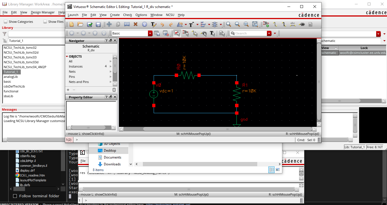
Next, the tutorial was launched in cell view to create a schematic.
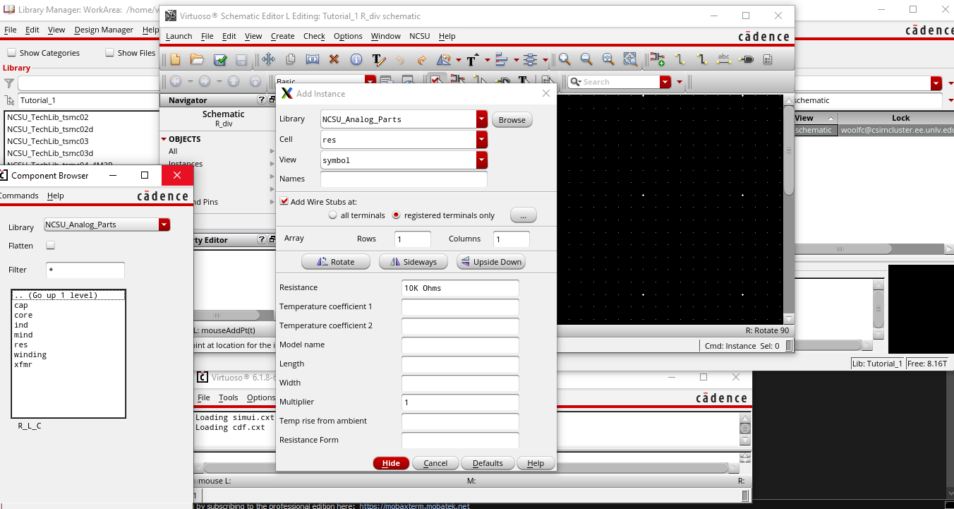
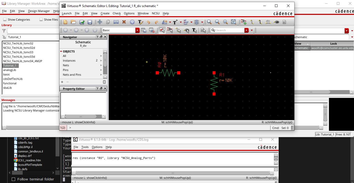
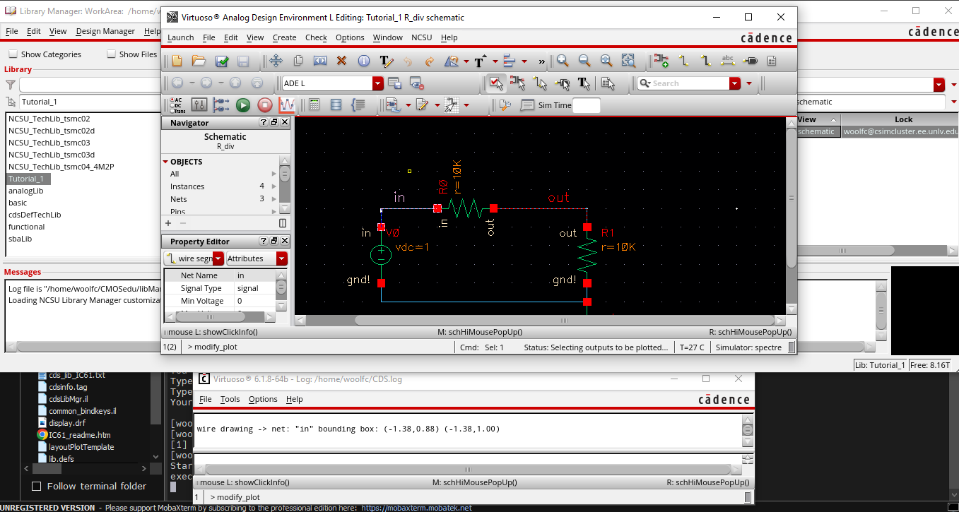
Then, using intance, place two resistors with resistance at 10kOhms.
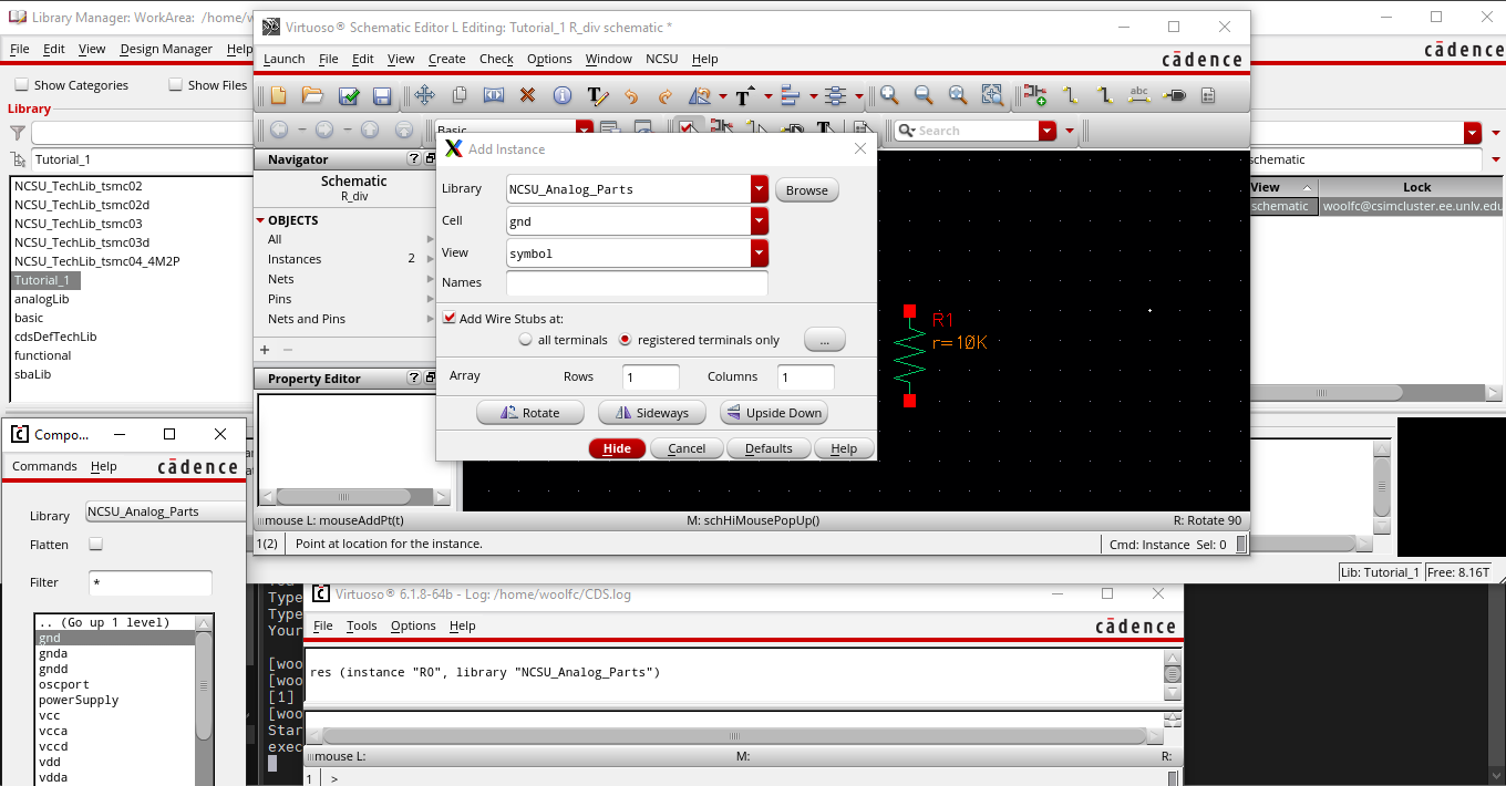
Next, a ground was placed.
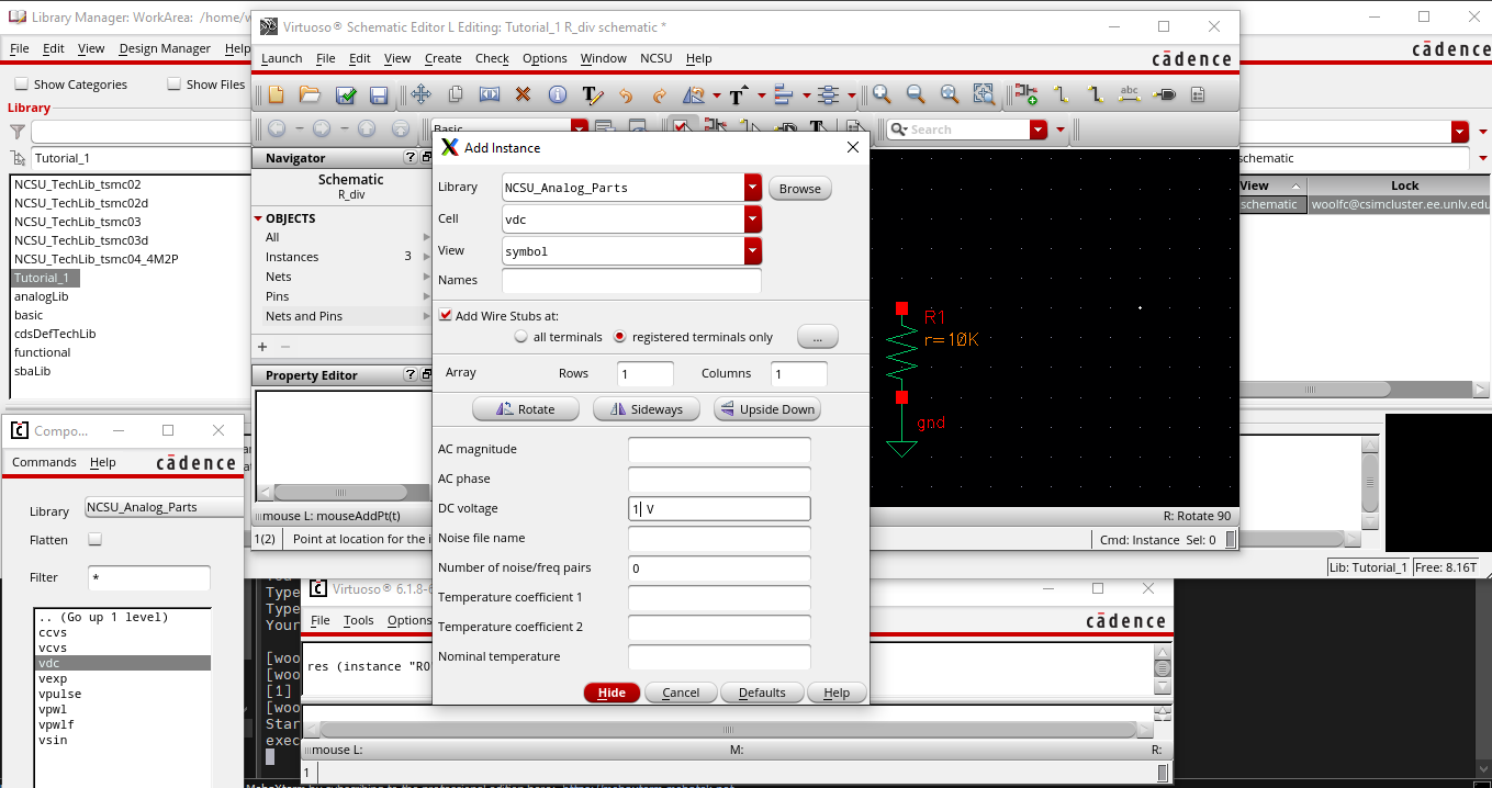
The next step required the addition of a voltage source.
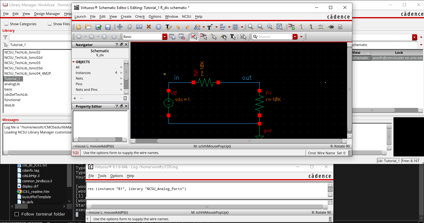
Wires are then added to complete the circuit.
Now, the wires are named.
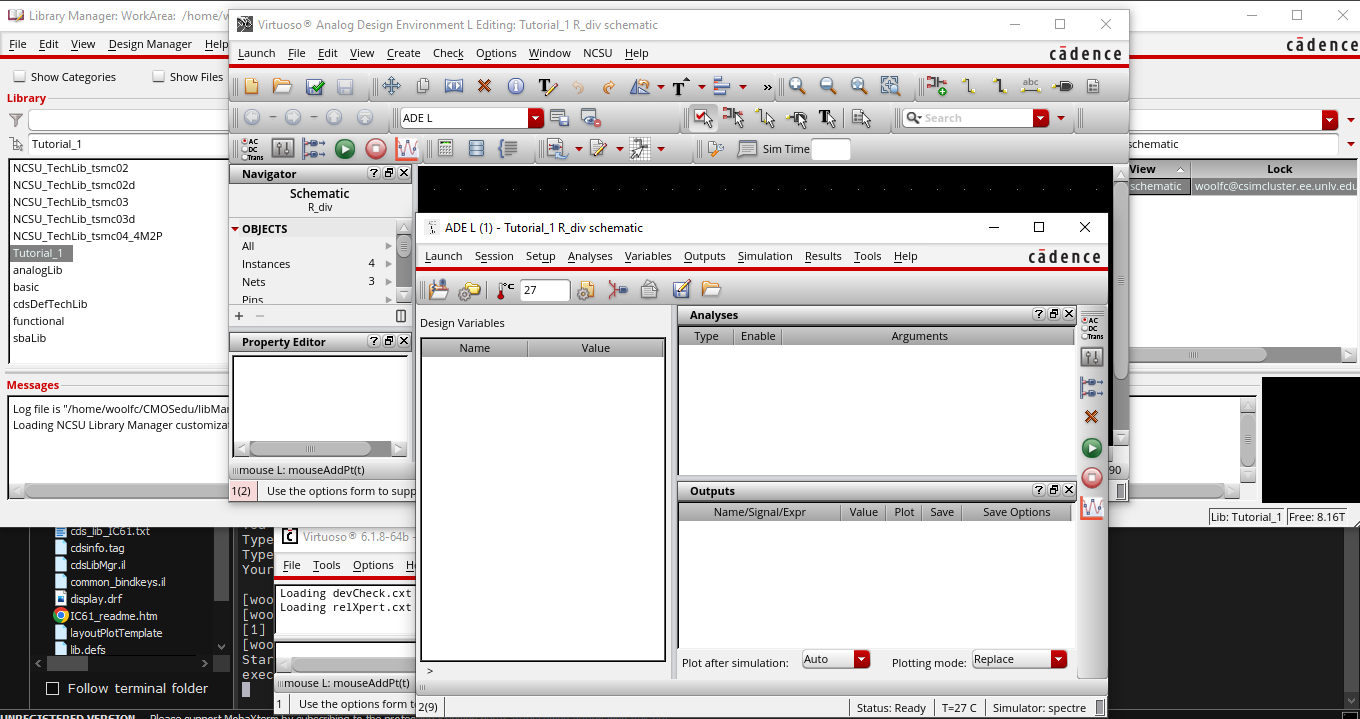
ADE L is selected from Launch.
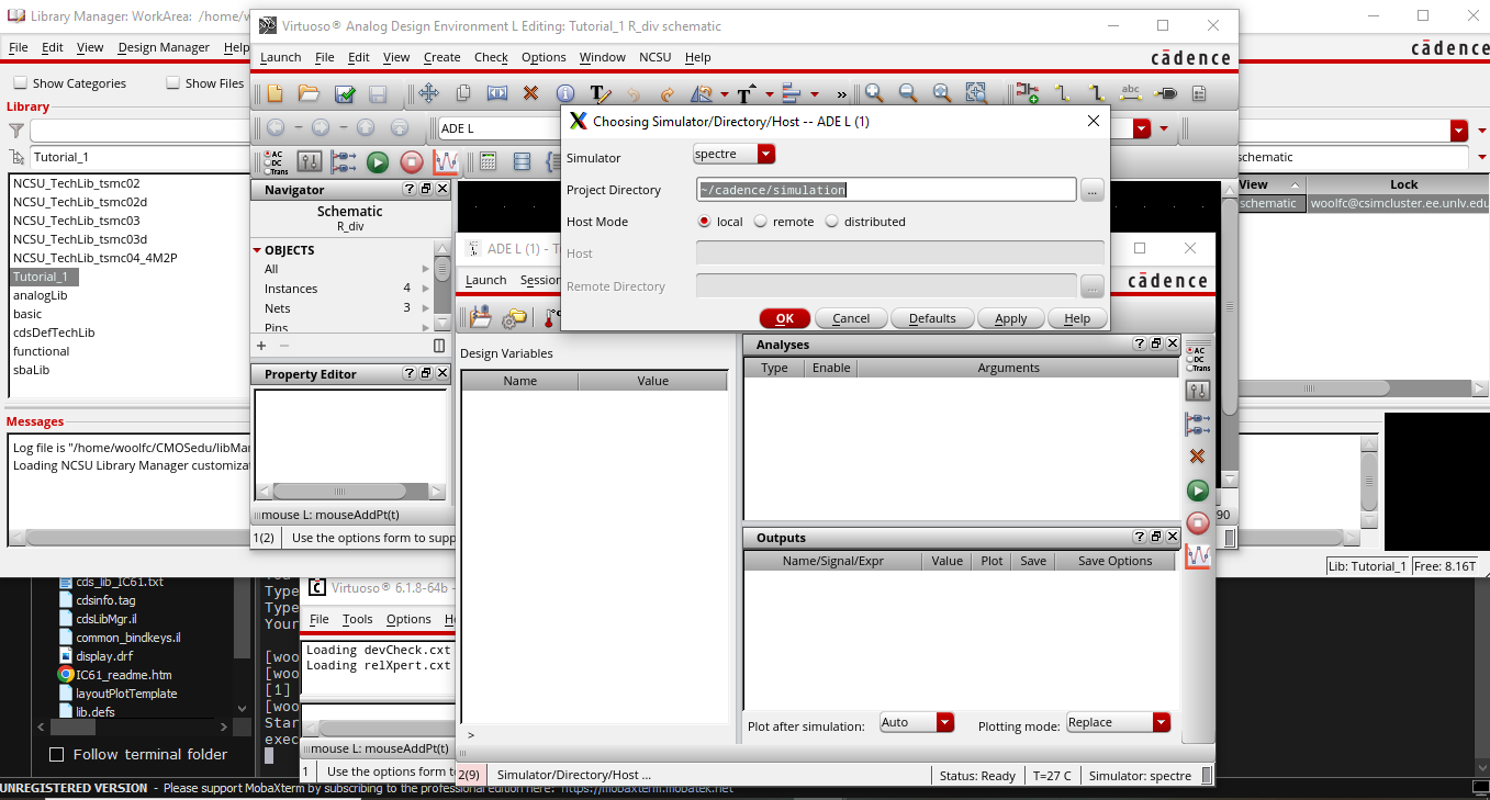
Next, verify that the simulation will run in spectre by selecting Setup -> Simulator/Directory/Host.
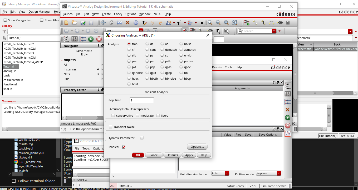
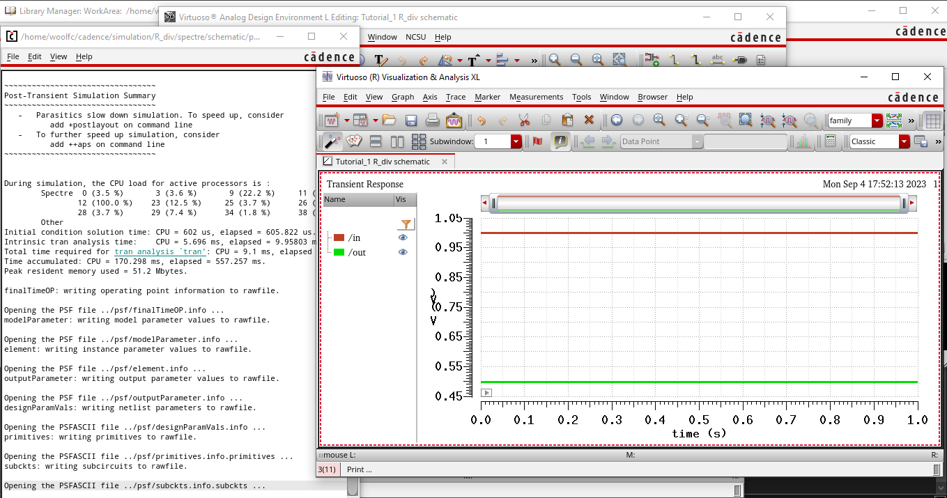
Run transient analysis by selecting Analyses -> Choose. Select .tran and set end time and enable.
The
next step required selecting Outputs -> To Be Plotted -> Select
on Schematic. Then select the wires labeled in and out.
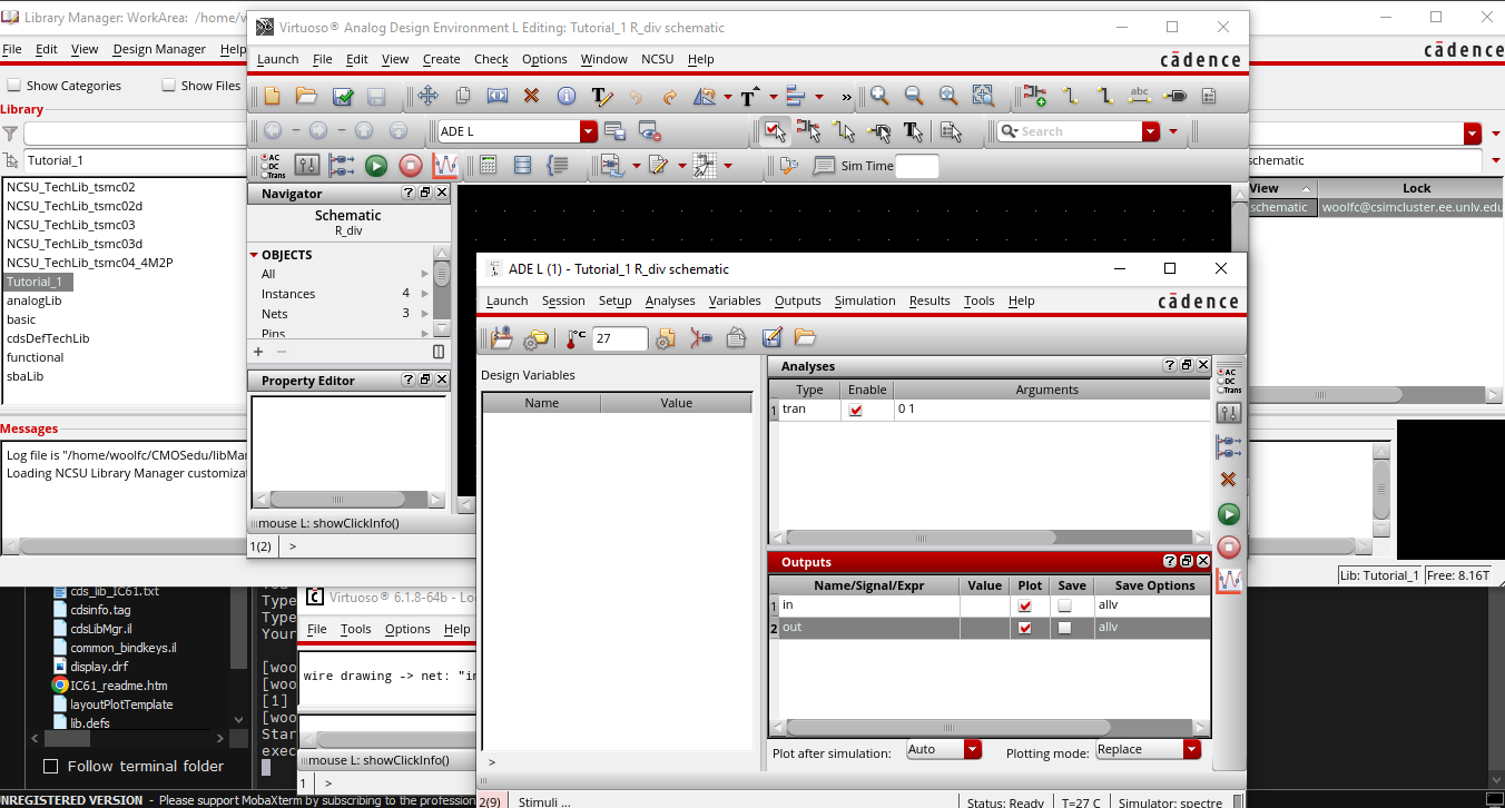
Ensure that the outputs to be plotted are selected on the ADE L window.
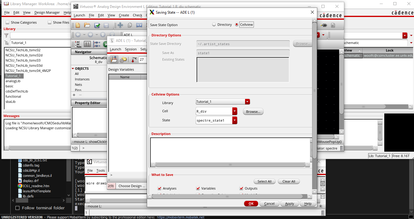
Prior to running the simulation, save the state for easier recall later.
Last, run simulation and collect results.
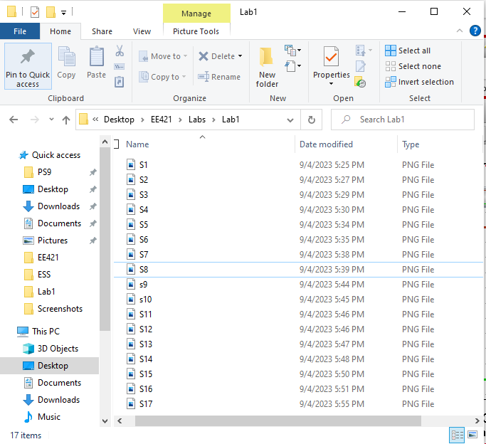
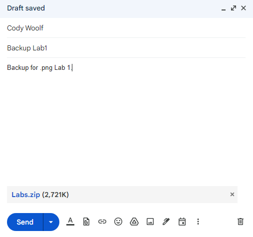
Backup of images accomplished by saving to desktop and emailing zip file to self.
Return to index