Lab 3 - ECE 421L
Layout of a 10-bit digital-to-analog converter (DAC)
Pre Lab:
This pre lab continues working through the tutorial that lab 1 started. Please see lab 1 for previous steps.
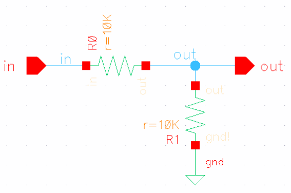
For this prelab we start with the schematic of our voltage divider that we will be turning into a symbol.
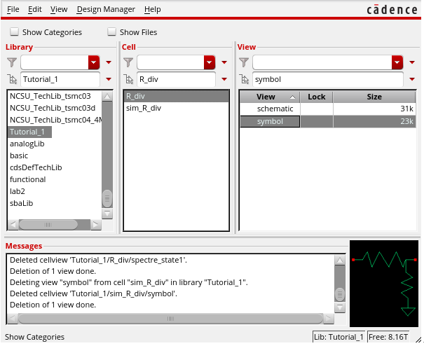
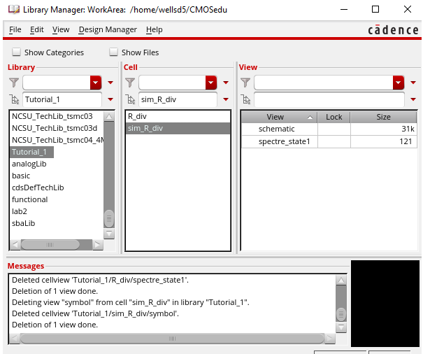
Next we copied the r_div cell that we were working in into sim_r_div and deleted the symbol from sim_r_div and deleted the spectre save from r_div. This way we can use the symbol from r_div in a circuit in sim_r_div.
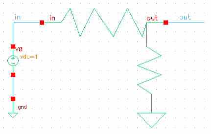
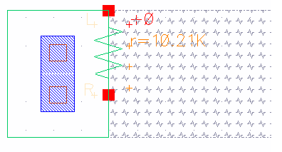
After we create our symbol as seen above, we implement it into a circuit by adding a voltage source.
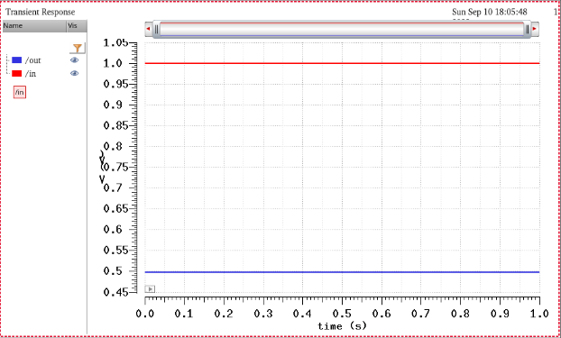
Next we run the simulation to make sure it runs as we need it to,
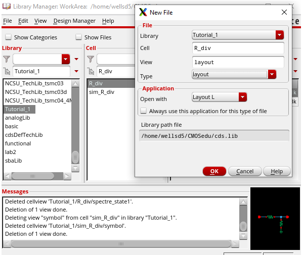
Now we can move on to making our layout. Next, we create the file we will be making the layout in.
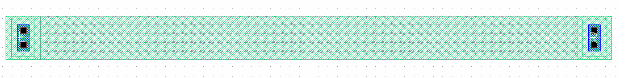
We use rectangles and carefully select layers to draw our resistor. By using the formula R = Rsquare * L/W, we can get the dimensions of the resistor that will operate at the desired resistance. For this tutorial we wanted a 10k resistor so we have a length of 56.1 and a width of 4.5.
Next we extract our resistor to verify the resistance value is what we want.
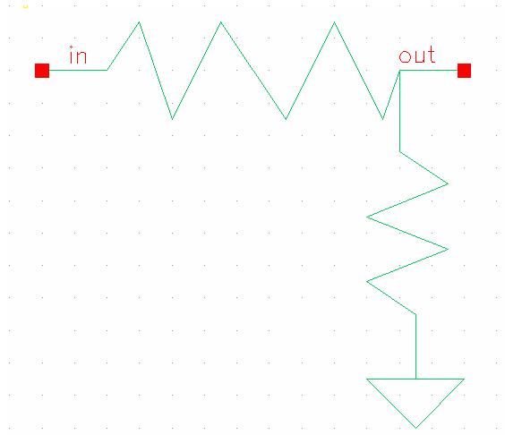
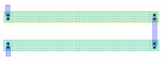
Now that we have verified the resistance, we can build our voltage divider by placing our resistors in a new layout view and using the metal1 layer to connect the contacts to make the connections of our circuit. We label our Vin, Vout, and gnd!.
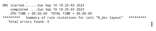
Now that it is built, we run DRC to make sure there are no errors.
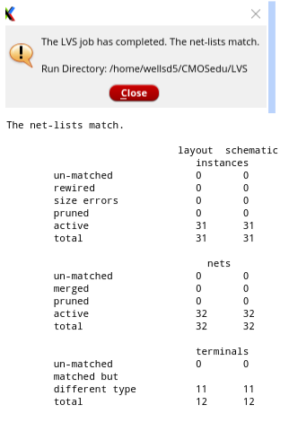
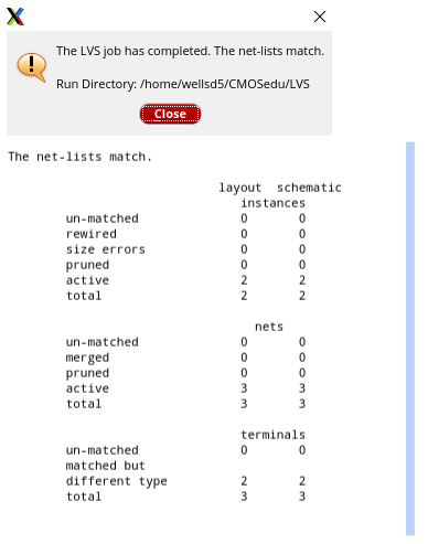
After we run DRC and have no errors, we run LVS with our layout and schematic both open at the same time. What we want is for our netlists to match.
______________________________________________________________________________________________________________________________
Lab:
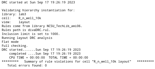
For this lab we use the 10k resistor we made in Tutorial 1 to create a 10-bit DAC that follows the schematic we created in the previous lab. The dimensions of that resistor by using the formula R = Rsquare * L/W. We chose a width of 4.5 and plugged it into our formula and got a length of 56.1. The following is the DRC of the single resistor.
Next
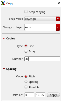
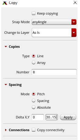
we needed to place one resistor, then use 'c' to make 30 copies of it
and by using 'c' to copy it, we can make sure they are perfectly lined
up with each other and are space with enough distance to meet the
required constraints of the system, that must be divisible by 0.15um.
After
we make copies of the resistor, we can do the same with our metal that
is making our connections to help save time and ensure uniformity.
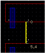
The ruler tool can be accessed by pressing 'k' and used to verify out distances.
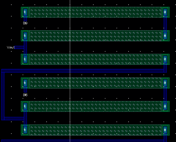
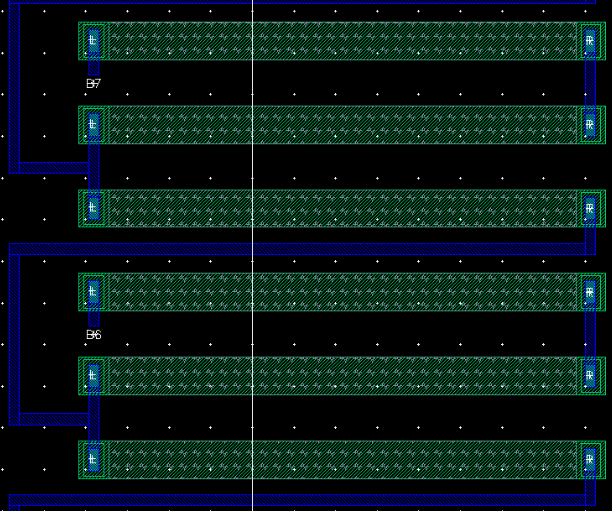
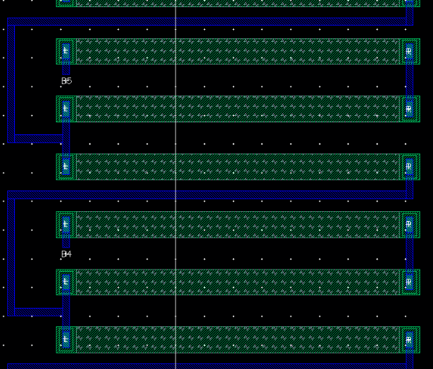
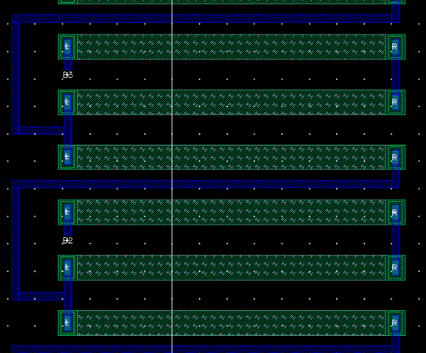
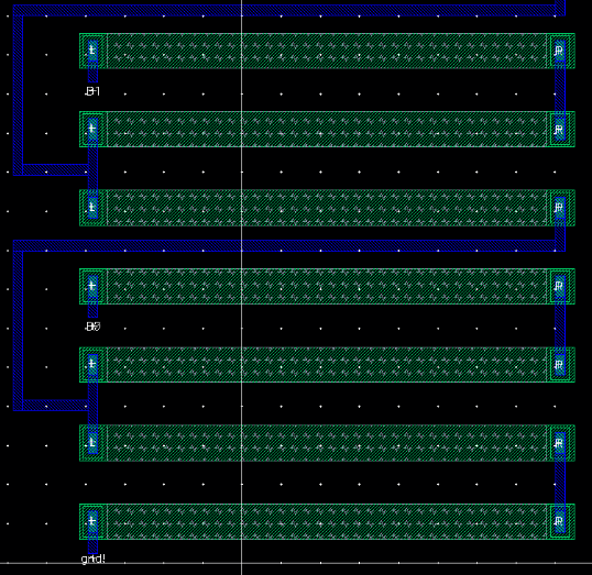
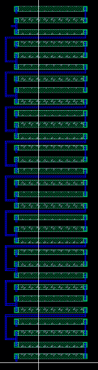
The following is what each bit looked like after all the connections and pins were laid out on all 31 resistors. Following that is what the entire layout of the DAC looks like.
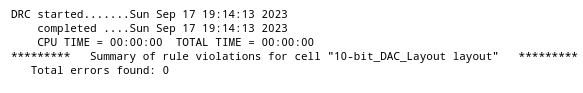
Next, we DRC our layout to check for errors.
Last, we LVS our extracted layout with the schematic to make sure the netlists match.