Lab 1 - ECE 421L
Prelab Description
The prelab consisted of getting our access to edit on CMOSedu from Dr. Baker as well as reading relevent information regarding html formatting on CMOSedu.com
Lab Work:
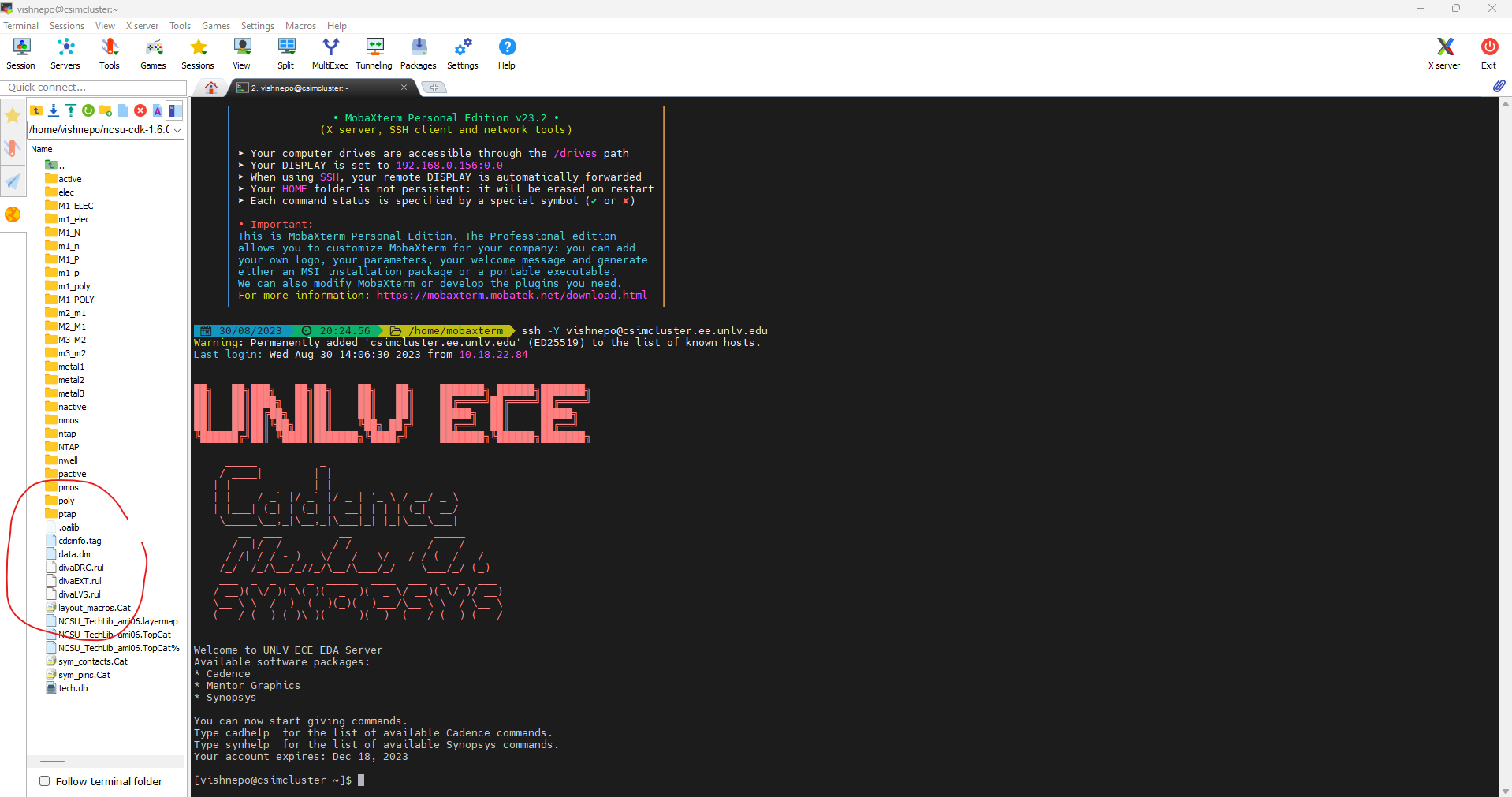
Before starting up Cadence using the virtuoso & command, I replaced the diva files as intructed. The reason the files require replacement is because of a bug in the beta version of the software.
After this, we are ready to continue with the tutorial. After launching cadence with the virtuoso & command, we set up our workspace by going to the library manager, creating a new library, attaching the correct tech library to it, and then opening a new cell view. The picture below shows all the windows that are opened immediatly prior to clicking ok and generating the workspace:
Then, I created instances of objects, searched for resistors, and plopped two down that had 10k values.
After that, we were instructed to add in ground, a voltage source, and wire it all up. In order to find all the obejcts in the circuit, you clicked "I", and found the parts within the NCSU_Analog_Parts library as shown in the picture below. In this specific example, I was searching for ground, which was found within the Supply_Nets folder of the NCSU_Analog_Parts library,
Once adding in all the componets to the circuit, I wired it up using bindkey "w", and labeled vin and vout using bindkey "l" (thats lowercase L, not I). The result looks like this:
After
that, we are ready to simulate the circuit. However before we sim we
have to ensure that the circuit is correct. This can be done using the
Check and Save button on the top right of the window. In the dialogue
box, you will recieve a message that there are no errors. If there are
errors, the simulation will not run.
Next
up, it is time to click "Launch", and select ADE L. Once opening the
window, there are a few things that need to be configured. Click Setup
> Simulator/Directory/Host
> spectre. Then go to analysis, and select tran for a transient
simulation. Select a time for 1 second. Then select Outputs > To Be
Plotted > Select on Schematic. This allows the user to click the
values he/ she wants plotted. Below is a picture where the tabs to be
edited are circled:
Once done, the page should look like this:
Before running the simulation, save the current state so that the user can always come back to these parameters for simming. The way you do this is byclicking Session > Save State.
Then, click the green play button and the result should look like this!

