Lab 1 - ECE 421L

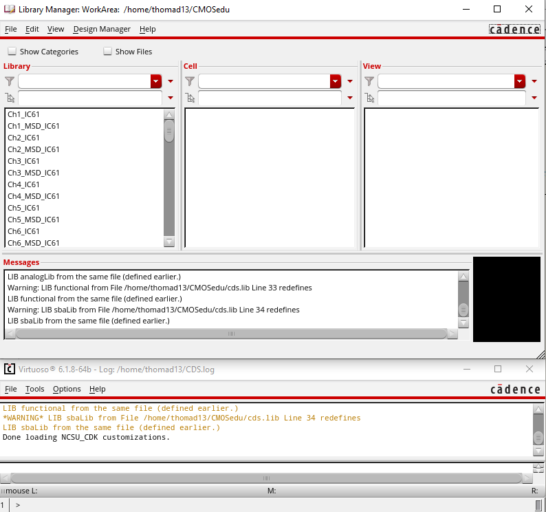
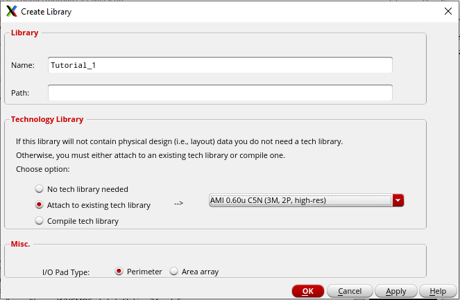
We then create a new library for Tutorial 1

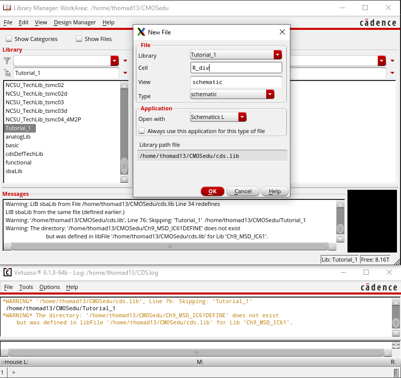
We create a new cellview in the newly created library

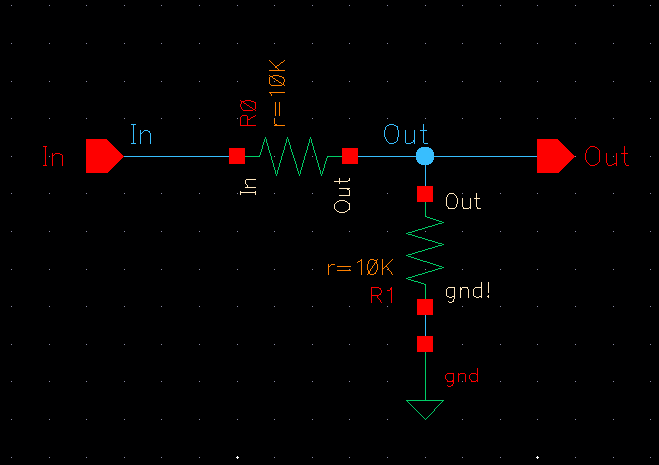
In that new cell view we add instances of 2, 10K Ohm resistors
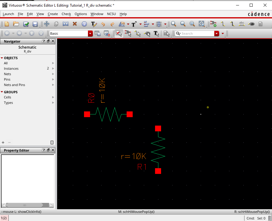
Similarly, we then add a DC voltage source and ground before wiring the circuit together.
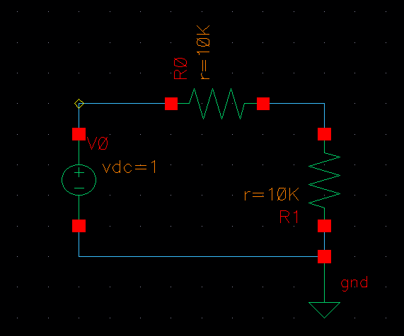

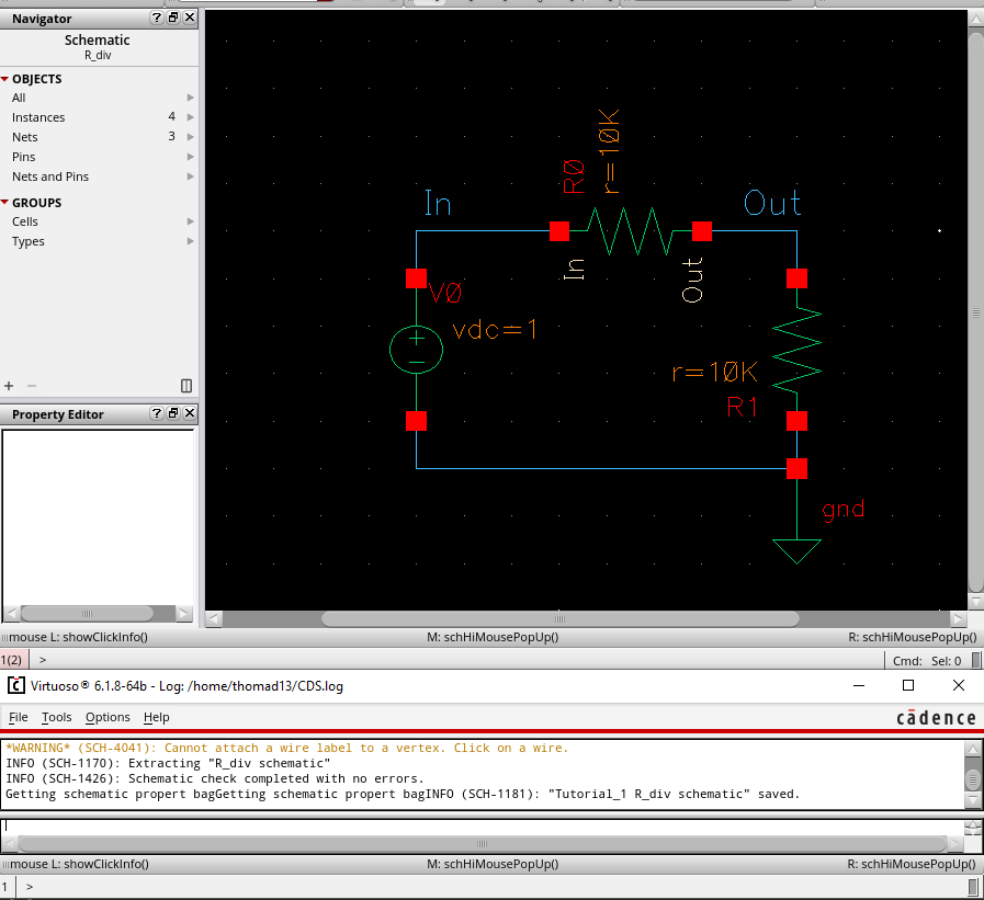
After wiring we label our wires and check and save our current schematic.

Now we begin the setup for our actual simulation
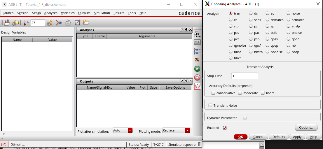

We then can add our outputs to be plotted and save the current state for later simulation.
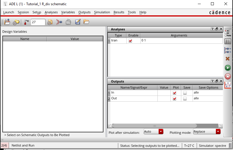

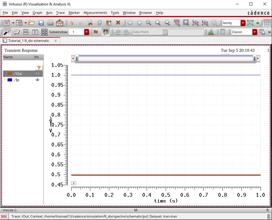
Now we are prepared to simulate this design.

Moving on, we alter the schematic with input and output pins.

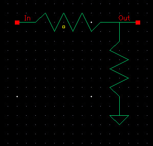
With this we can create a symbol for this schematic.


Altering the symbol and adding a line drawing we are left we are left with the following.

With these completed we move back to the library manager where we copy the R_div cell and delete the spectre_state1 view
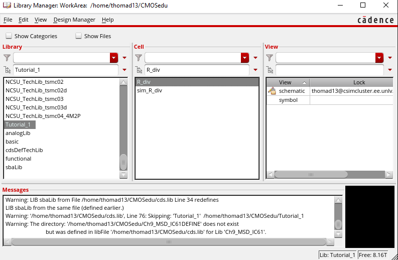

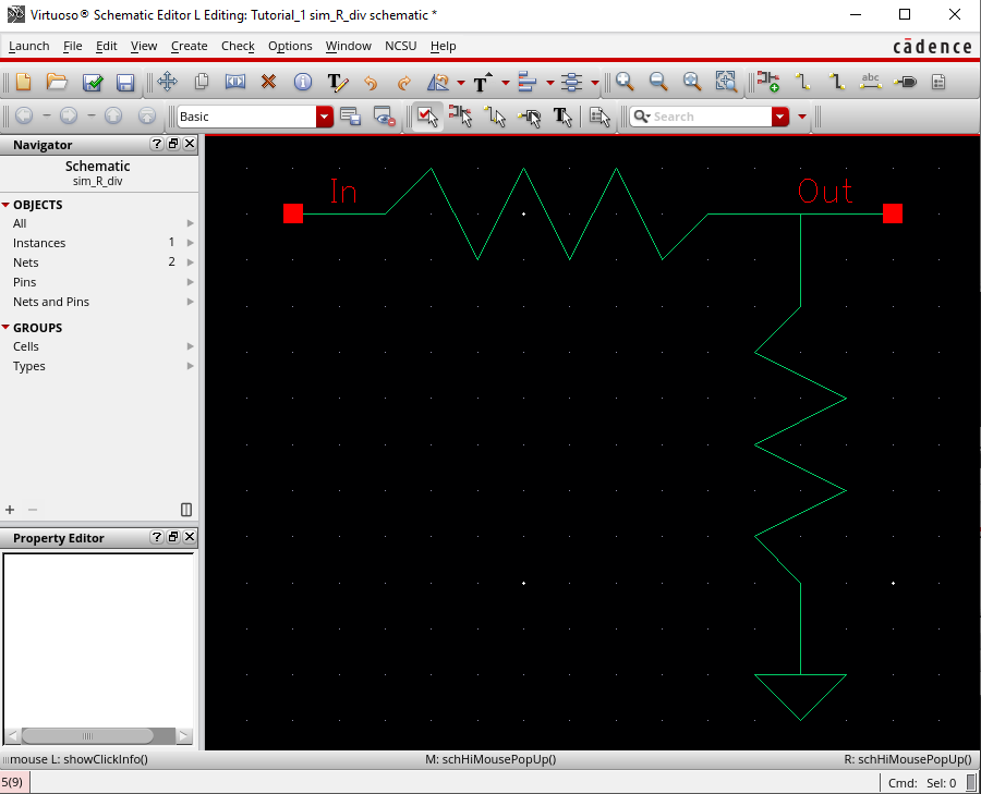
We then alter the sim_R_div schematic and place the R_div cell from the Tutorial_1 library
 http://cmosedu.com/jbaker/courses/ee421L/f23/students/

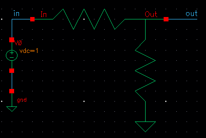
We can then add a voltage source, ground, and wires as before

Launching the ADE again, we can reload the state from earlier, choose our outputs to be plotted and simulate again.
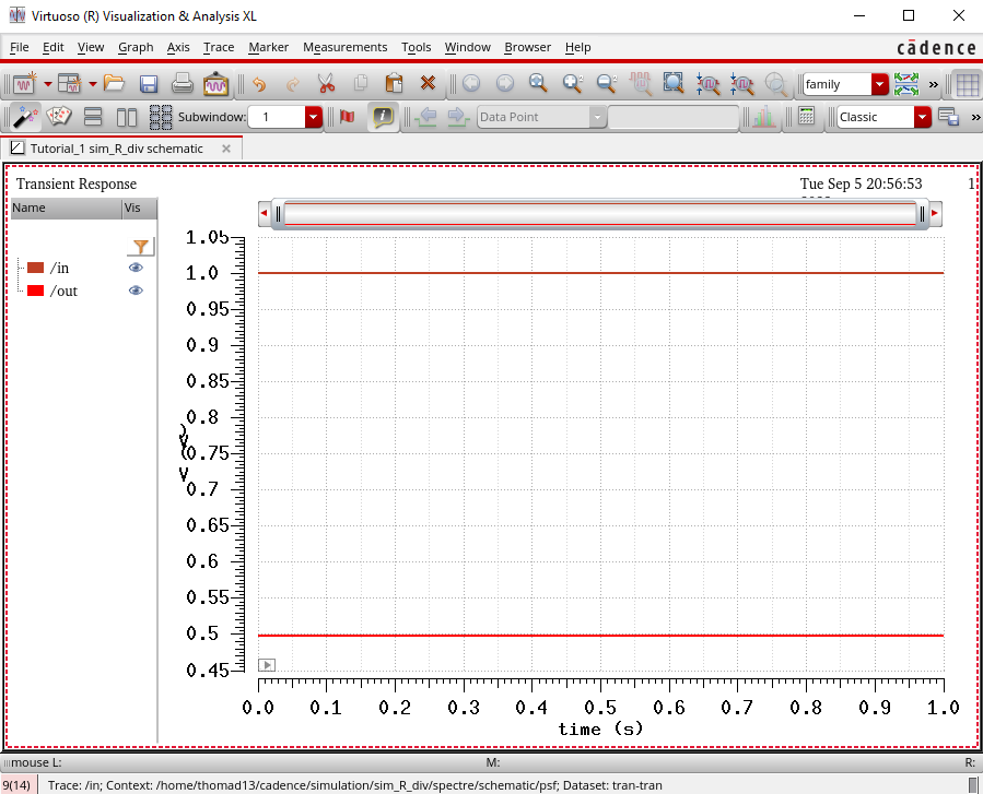
With the simulation finished the Cadence portion of this lab is completed.
2) I will be doing regular backups via uploading a zipped folder to my google drive.
