Lab 1 - ECE 421L
Authored
by Jalen Solis, solisj8@unlv.nevada.edu
September 5th, 2023
Pre-Lab
Prelab
consisted of emailing Dr. Baker to receive an account for CMOSedu.com.
Once we recieved our account with a username and password, we
accessed our own directory within the website. We then downloaded the
lab.htm template along with the KompoZer software to be able to edit
and publish our own lab reports. Finally, we followed a short tutorial
to set up a mock lab report and have it published on the CMOSedu
website.
Lab
The
purpose of this lab is to practice setting up and using Cadence for
simple circuits as shown below. We will be practicing using tutorial 1
from the Cadence design system tutorials from CMOSedu.com
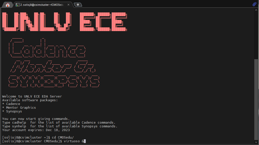
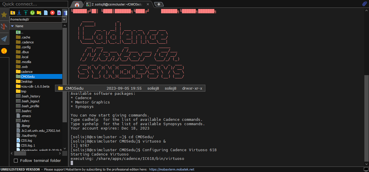
First thing to do is to access Cadence from the MobaXterm software:
- We need to make use we are in the right directory, to do this type "cd CMOSedu"
- To launch virtuoso we must type "virtuoso &"
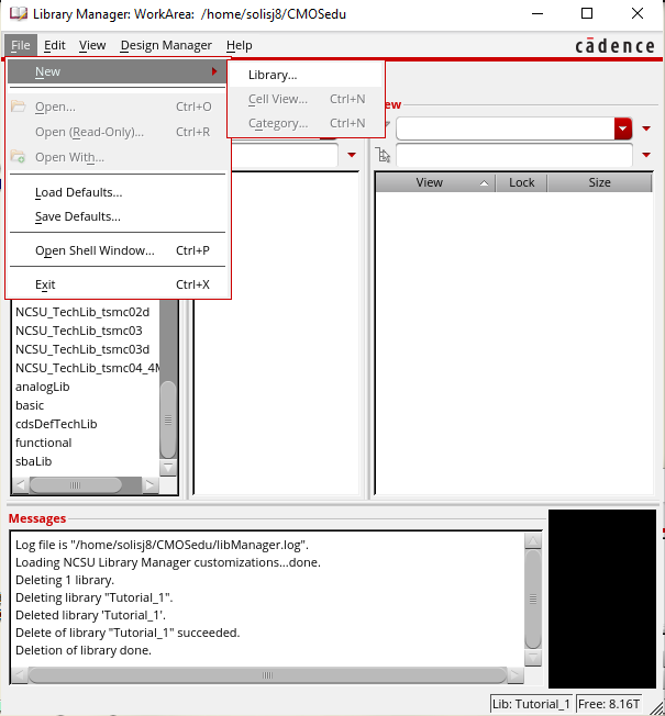
Once we launch virtuoso we navigate to the library manager and create a new library:
- Click "File"
- Click "New"
- Click "Library"
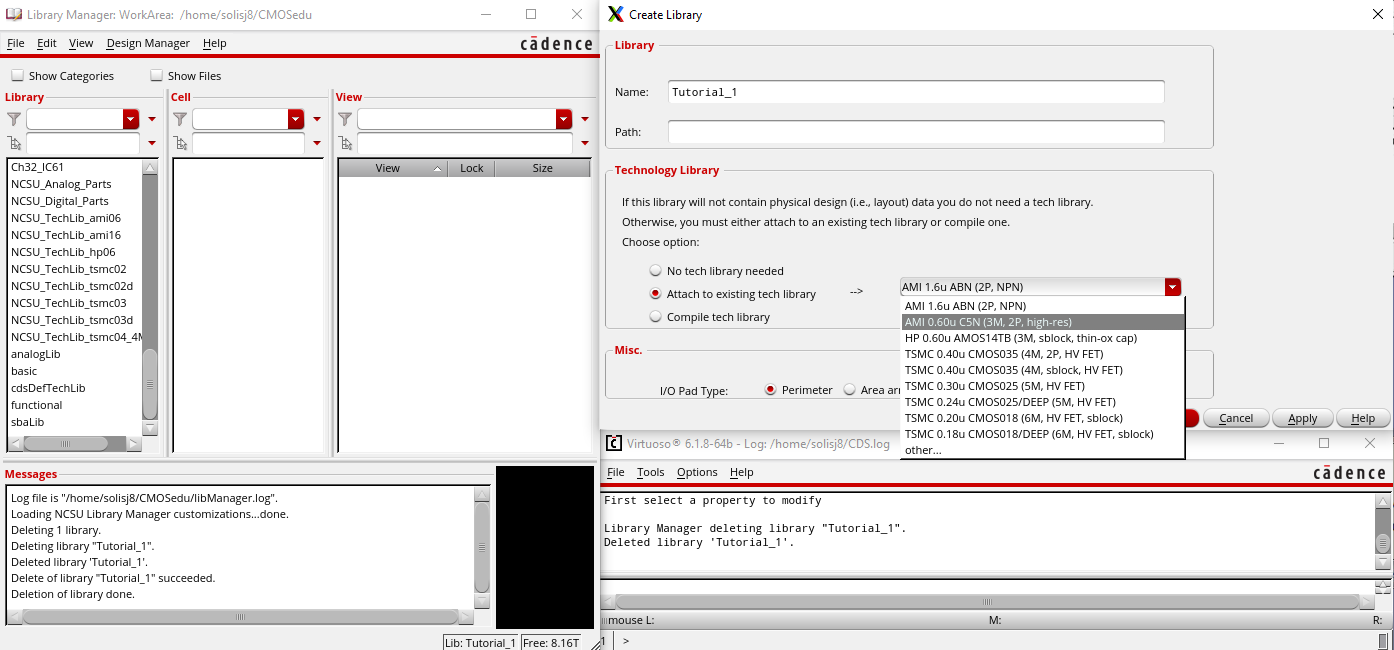
A
new window will pop up titled Create Library and in that window we will
give a name to our new library along with setting up some parameters:
- Give library name "Tutorial_1"
- Select "Attach to existing tech library"
- Click the dropdown bar and select "AMI 0.60u C5N (3M, 2P high-res)"
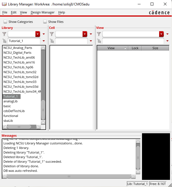
After clicking ok we can see in the library section of the library manager that a new library has been made titled "Tutorial_1"
To
verify that a new library has been made we can navigate back to our
Cadence terminal where we can locate our cds.lib file which should have
a new define with our library in it:
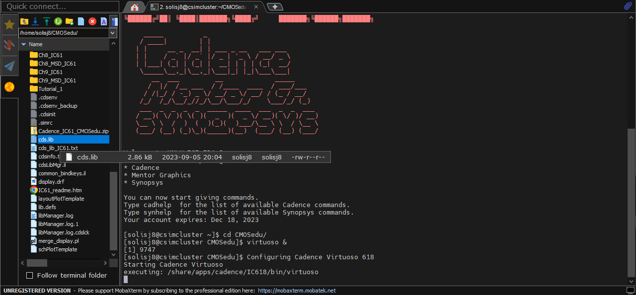
- Navigate to Cadence terminal window and select the "CMOSedu" folder
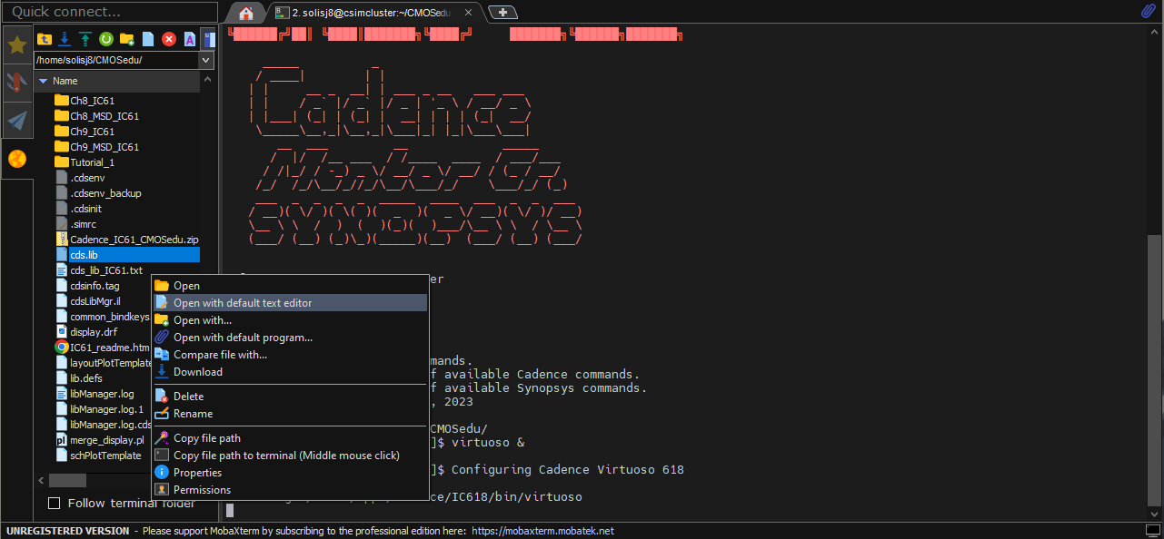
- Within the folder locate the "cds.lib" file
- Right click and select "Open with default text editor" to view document
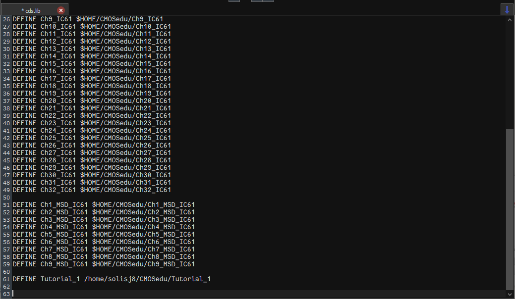
After opening the cds.lib file navigate to the bottom:
- There should be a line that reads "DEFINE Tutorial_1" along with the file directory path
After verifying we can navigate back to the library manager and create a cell view:
- Click "File"
- Click "New"
- Click "Cell View"
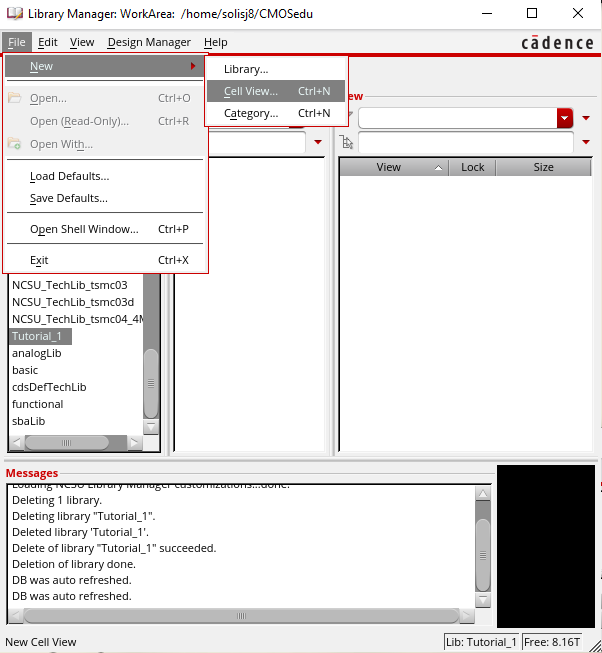
Another window will pop up which will allow us to name our cell:
- Name the cell "R_div" and select OK
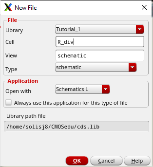
After naming our cell, another window will pop up which will be our schematic editor to create a simple circuit
First we will place our resistors:
- Head over to the "Create" tab
- Select "Instance"
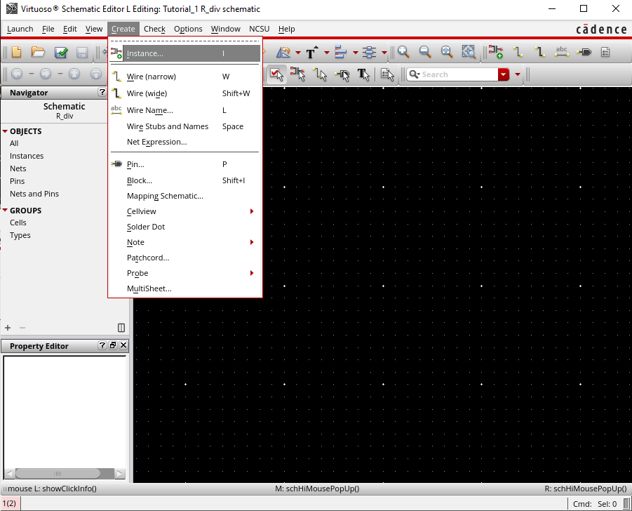
Another window will pop up titled "Add Instance" where we can add different electrical components:
- For the Library select "NCSU_Analog_Parts"
- For the Cell select "res"
- For the Resistance type in "10k"
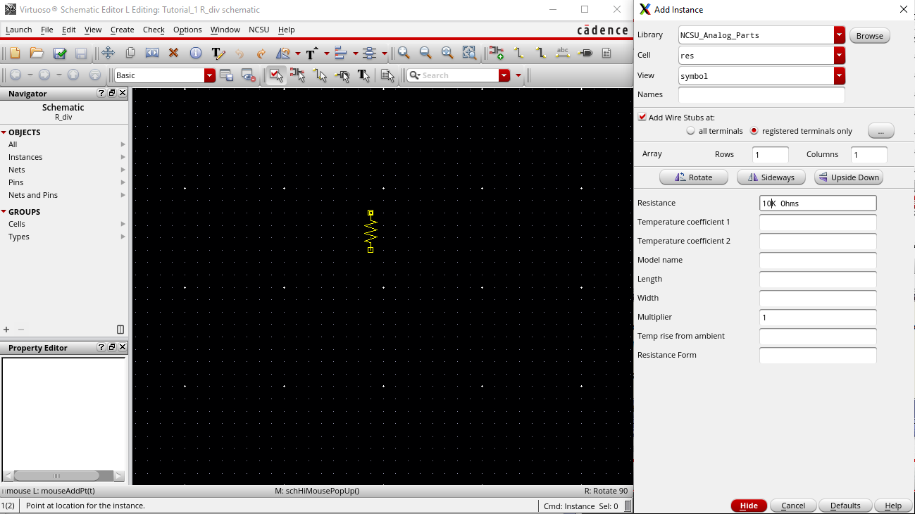
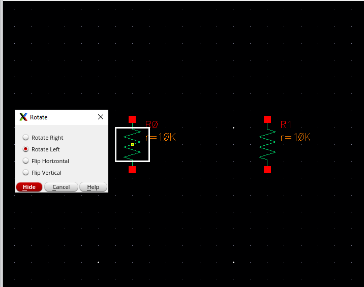
Once
we have our parameters set we can hover our mouse over the grid and see
that we can place the resistor anywhere on the grid:
- To rotate our resistor we hit "R" on our keyboard and select the component we want to rotate and which way we want to rotate it
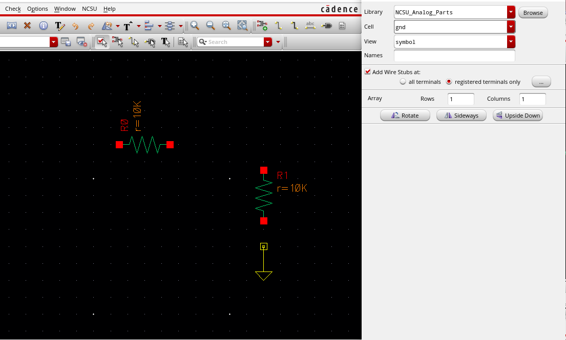
We will then follow the same process for inserting a resistor to add a ground:
- Head over to the "Create" tab
- Select "Instance"
- For the Library select "NCSU_Analog_Parts"
- For the Cell select "gnd"
- Go back to grid and select a spot to place
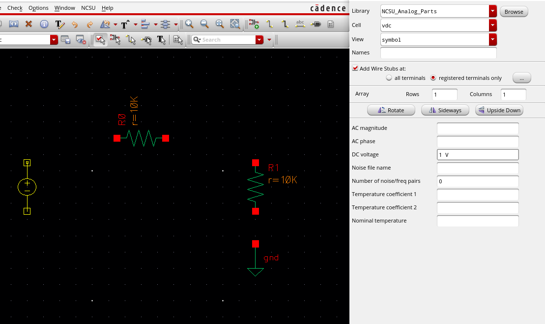
We will again follow the same process for adding the ground and resistor to add a voltage:
- Head over to the "Create" tab
- Select "Instance"
- For the Library select "NCSU_Analog_Parts"
- For the Cell select "vdc"
- For the DC voltage type in "1"
- Go back to grid and select a spot to place
Next we will connect everything with wire:
- Select the wire button or press "W" on the keyboard
- Connect each red square with each other until everything is connected
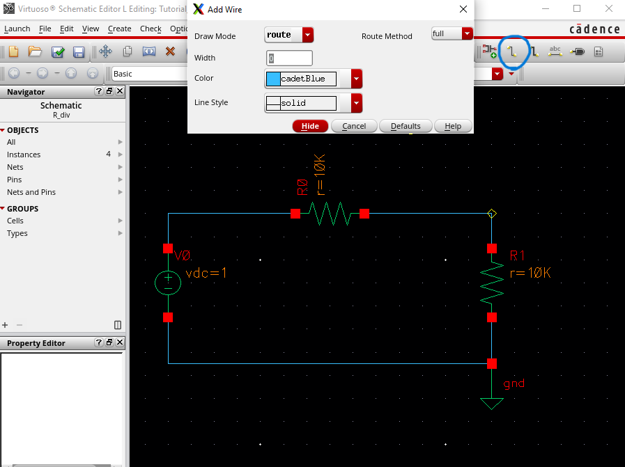
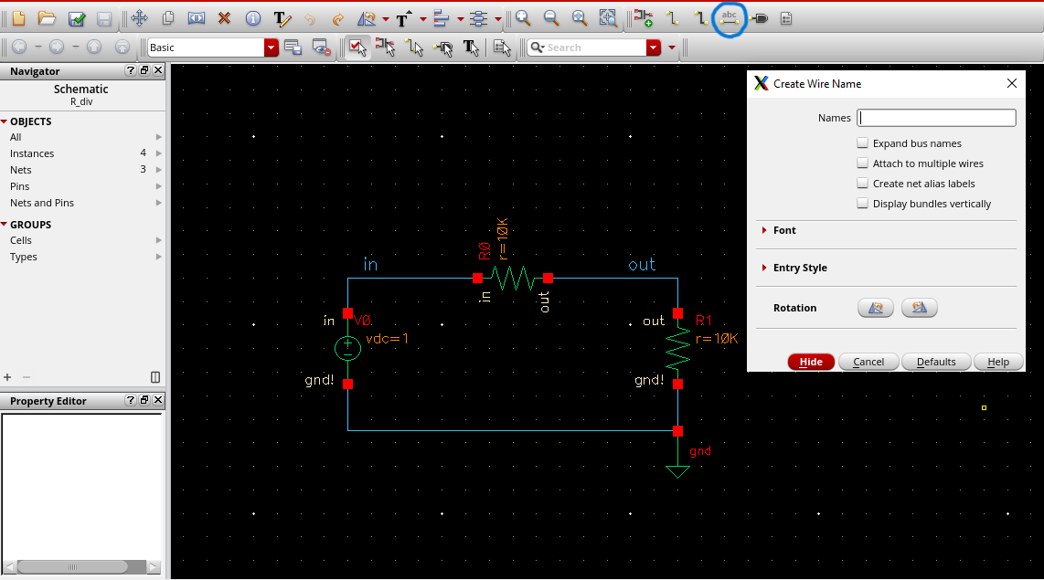
We will now create wire names that way we can use them for our plots:
- Select the line name icon
- Type in "in"
- Place on line above voltage source
- Type in "out"
- Place between both resistors
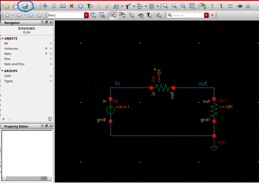
After we complete our circuit we must check and save our schematic before we can plot its outputs:
- Click the "Check and Save" icon
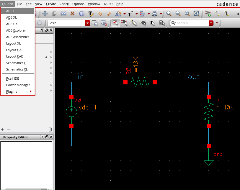
Now that the circuit is completed we can simulate with Spectre:
- Click "Launch"
- Click "ADE L"
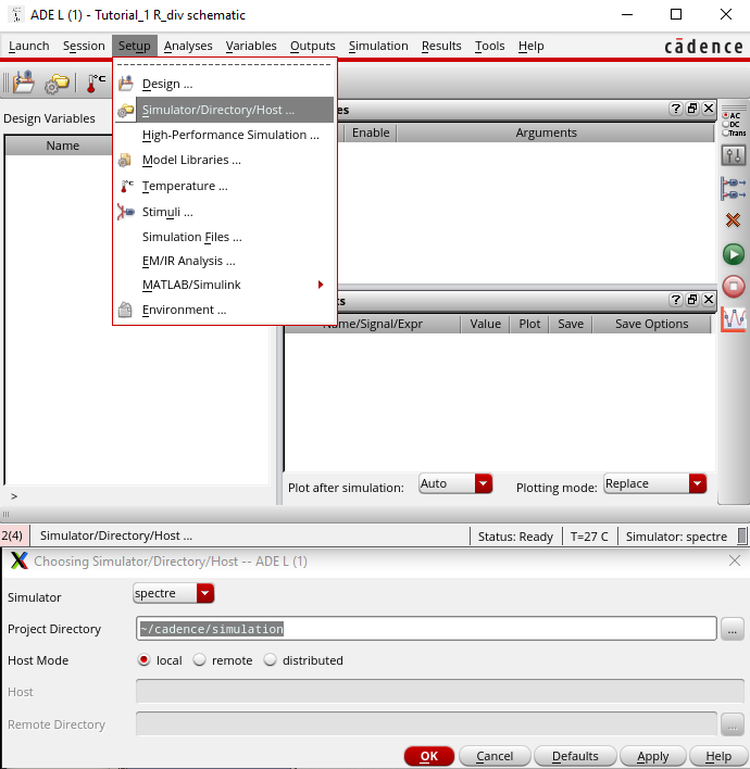
We must verify that our simulator launched with Spectre:
- Click "Setup"
- Click "Simulator/Directory/Host..."
- A window will pop up which will show which simulator we are using
- Verify that the simulator is Spectre
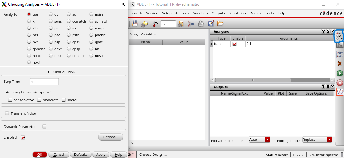
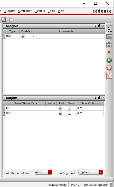
After verifying that our simulator is correct we can select which type of analysis we want for our circuit:
- Click the icon on the right side of the window
- Within Analysis select "tran"
- For Stop Time type "1"
- Make sure Enabled has a checkmark next to it
- Select "OK"
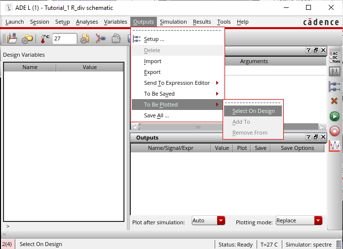
Once we have the type of analysis we want, we must select which outputs we want to be plotted:
- Select "Outputs"
- Select "To Be Plotted"
- Select "Select On Design"
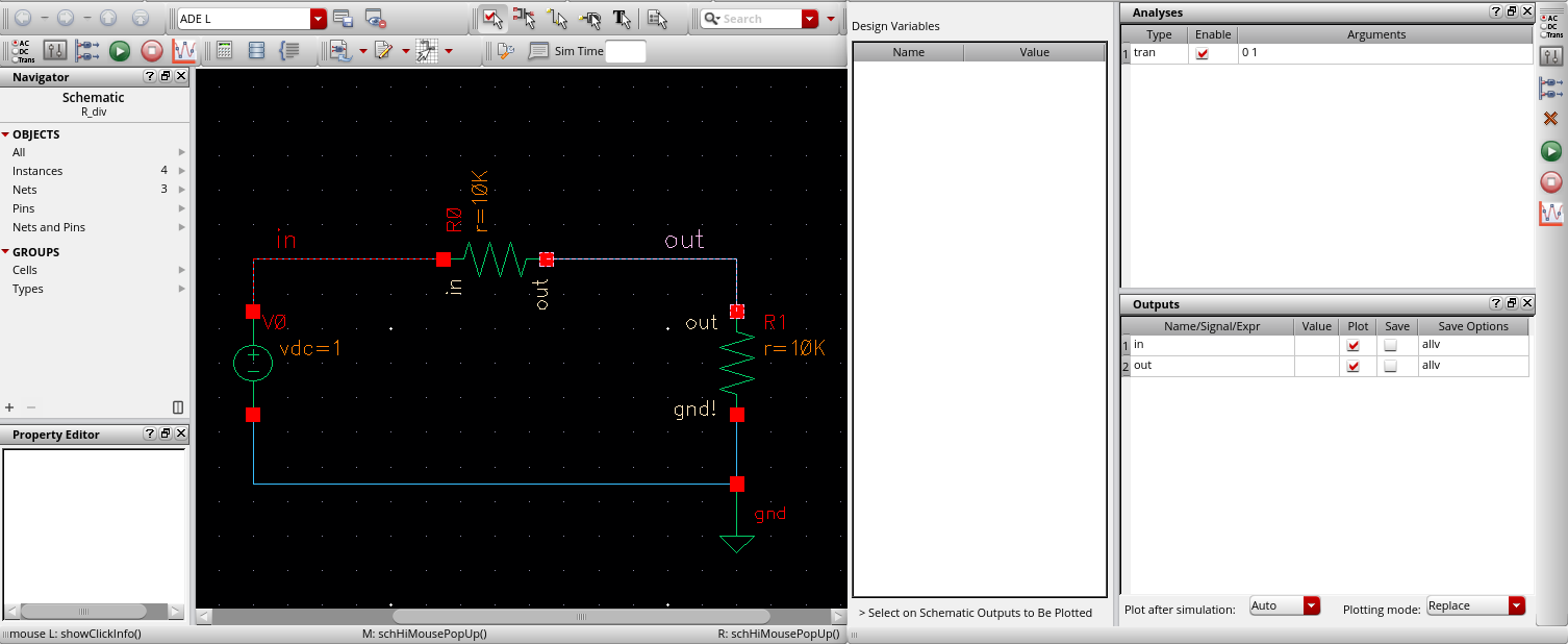
After that we must select which points we want to be plotted from the grid
- On the schematic select the wire with the label "in"
- On the schematic select the wire with the label "out"
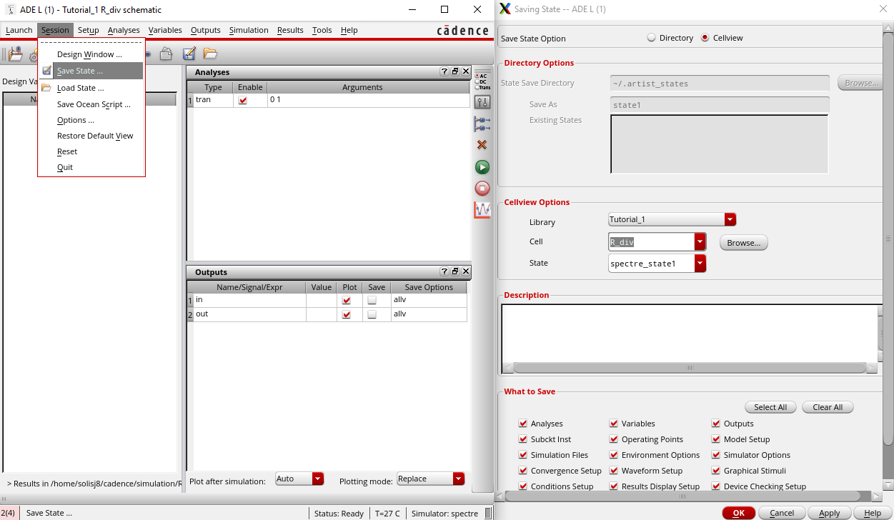
Now that we have everything ready to be plotted we must save our work:
- Click "Session"
- Click "Save State"
- Verify library name and cell name are correct
- Click "OK"
After saving we can click the green circle and see the plots of our voltage in and voltage out from the circuit
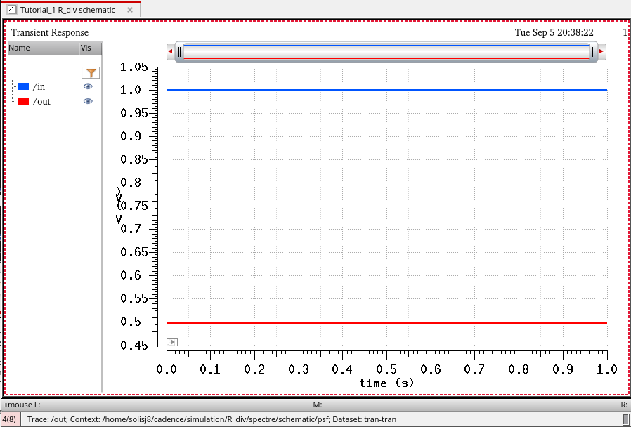
Our final result will be a plot with both the input voltage and the output voltage
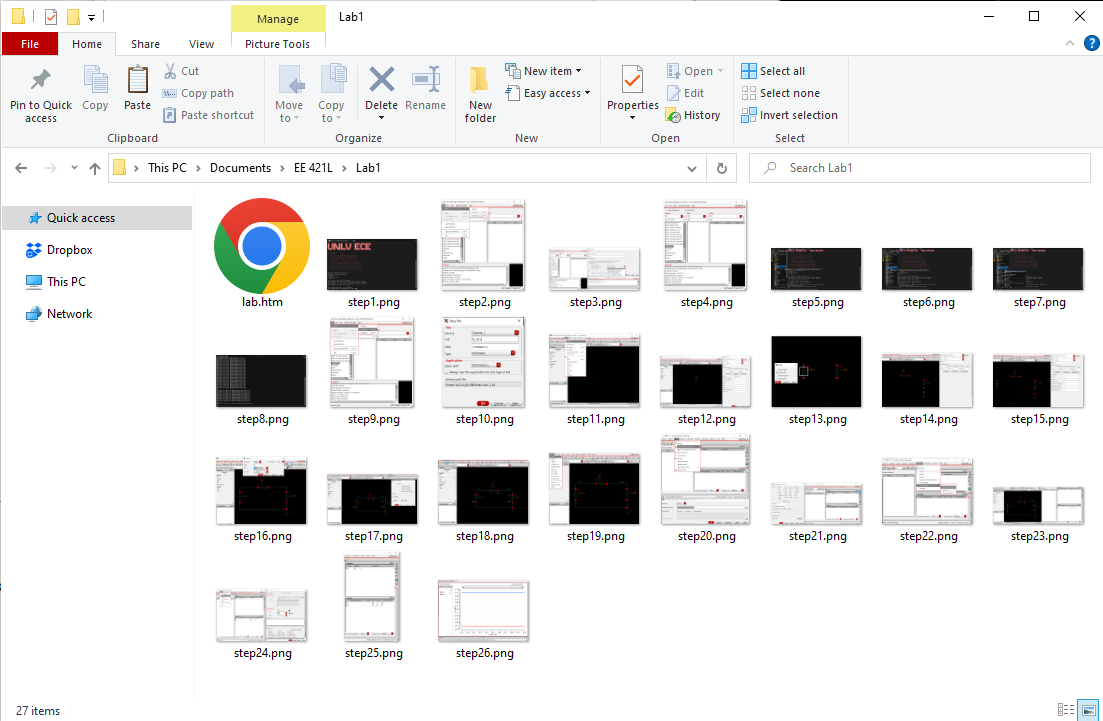
Backing up work is important especially when dealing with large amounts of data.
In
order to keep my images and files safe from being lost or corrupted I
will keep a zip folder along with a regular folder full of my files for
each lab.
The regular folder will be stored on my personal computer for easy access:
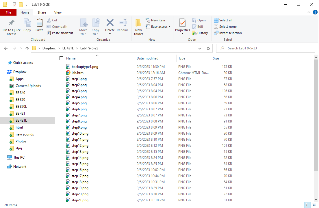
The zip folder will be placed in my Dropbox so that I may access it anywhere:
Return to EE 421L Labs