- Make sure nmos is 6u/0.6u and pmos is 12u/0.6u and the ntap and ptap have 2 columns respectivly
Align the Cells and DRC your layout

Save Your design
Add pins and exctract your layout
Lab 5 - ECE 421L
Finish Tutorial 3
Copy Tutorial 2 into Tutorial 3 and make sure to select Updated Instances so the library can be independant.
Next Create a Cell View Named inverter that is a schematic
Open NMOS_IV schematic and with both windows open press c to copy the transistor to the inverter window by dragging it.
Instantiate VDD and GND supply nets
Press w to wire the inverter and add pins
The A pin should have an input direction and pin Ai should have an output direction.
Lab 5
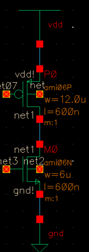
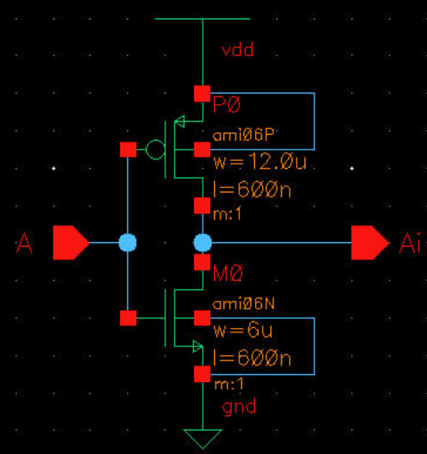
Creating a 12u/6u Inverter:
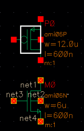
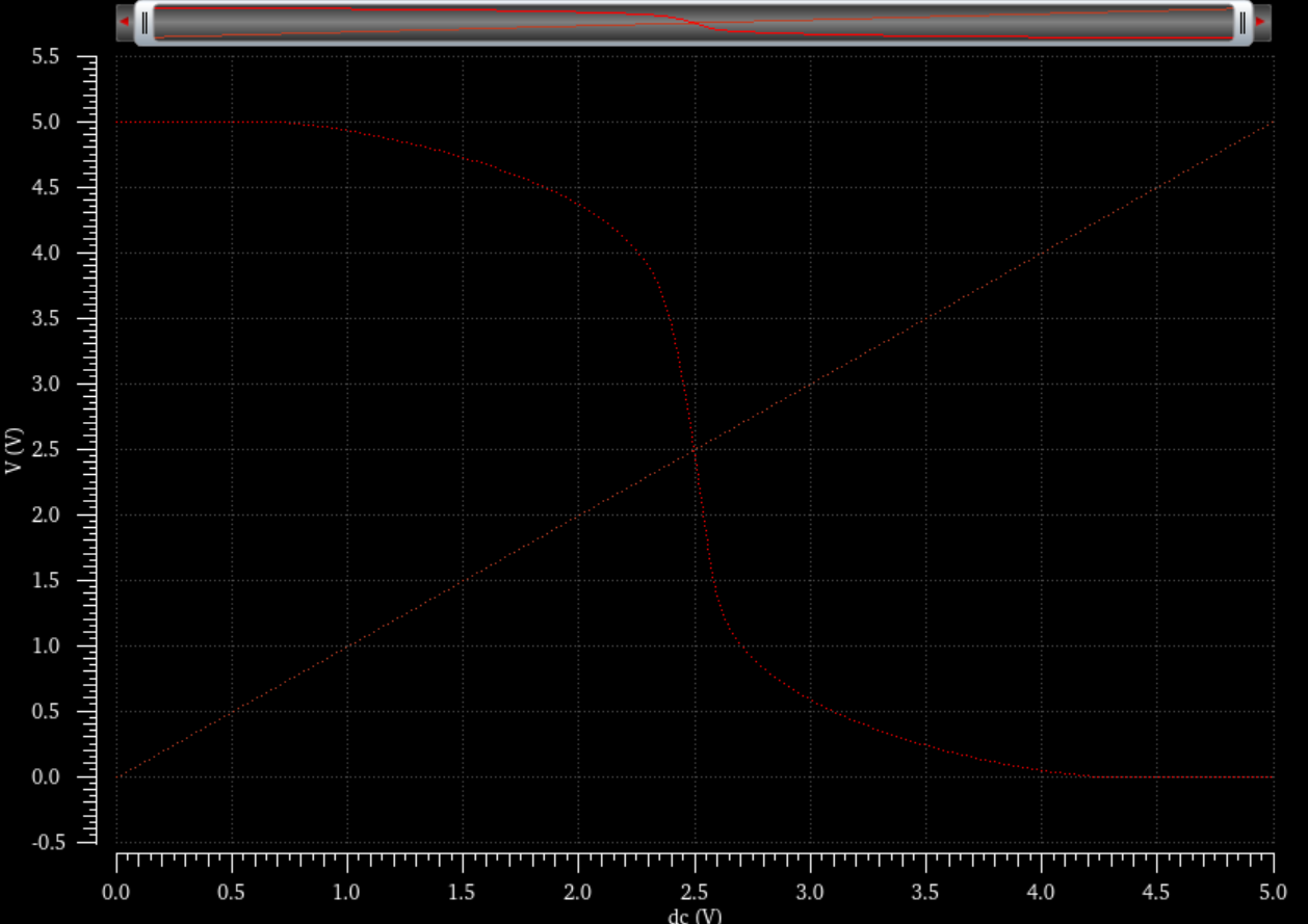
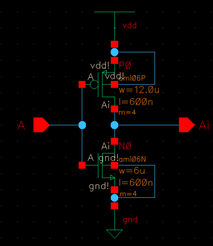
Schematic of NMOS-PMOS inverter:
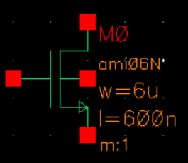
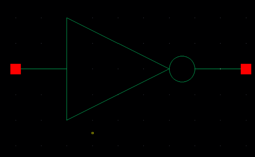
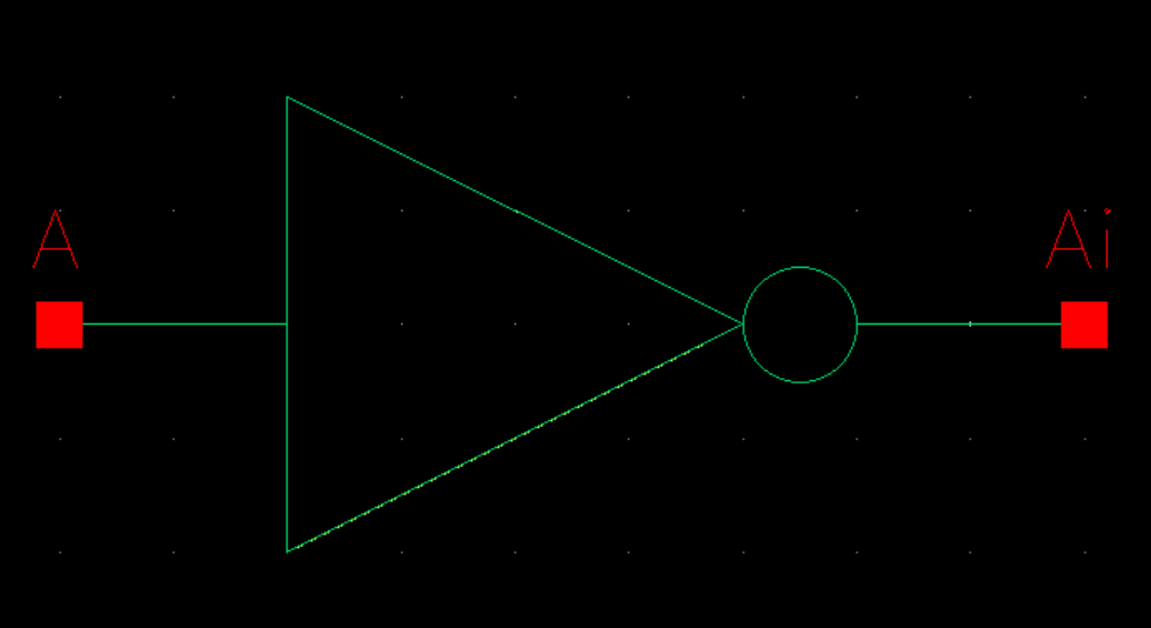
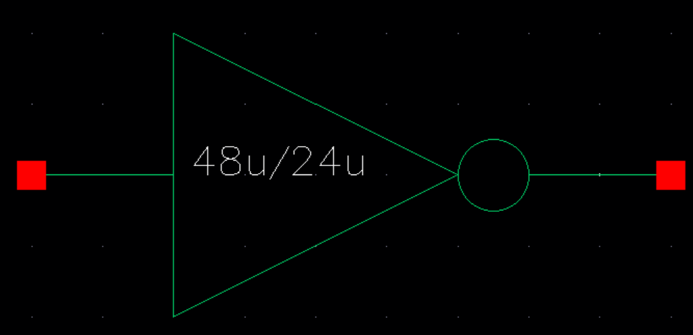
Inverter Symbol:
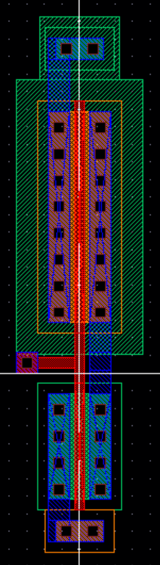
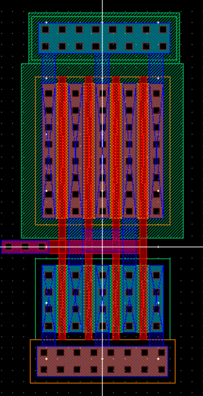
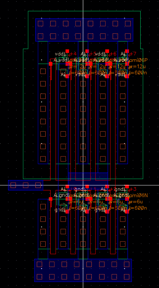
12u/6u Inverter Layout:
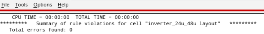
DRC the layout:

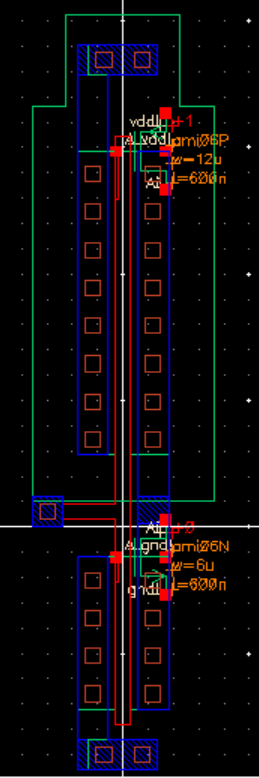
12u/6u Inverter Extracted View
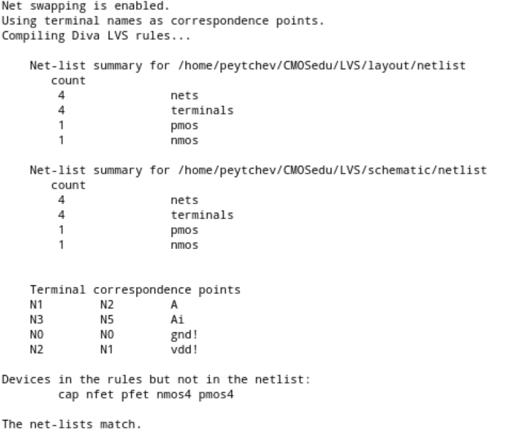
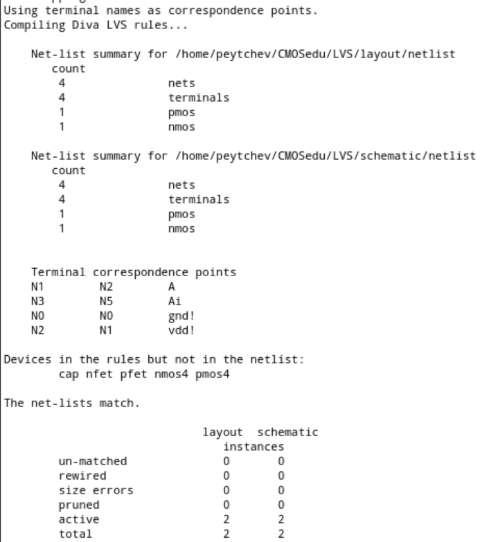
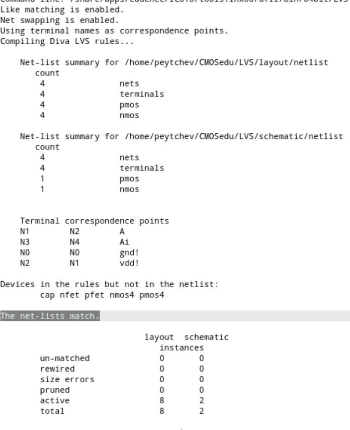
LVS:
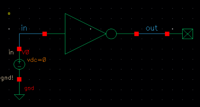
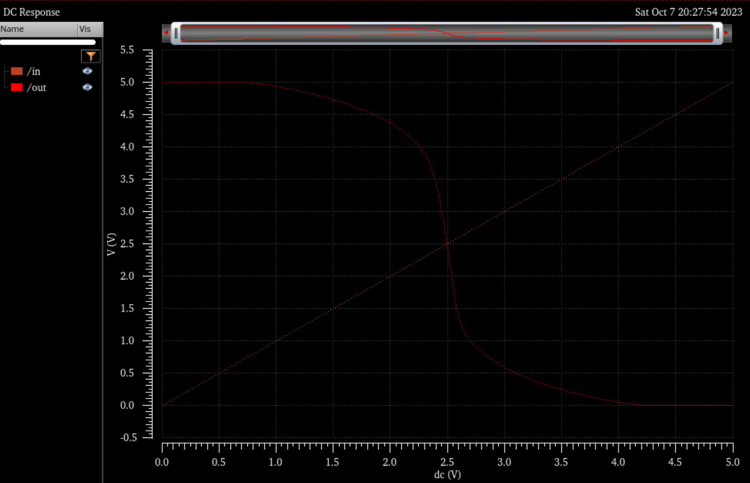
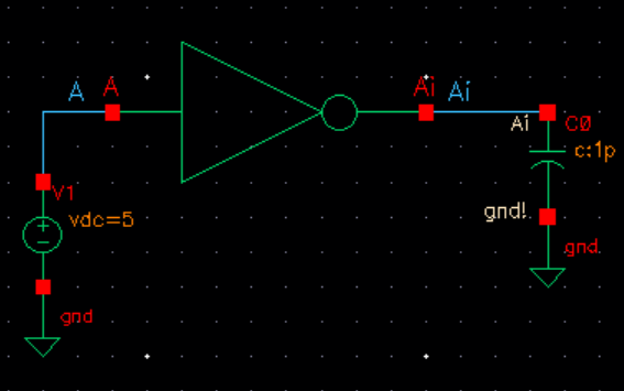
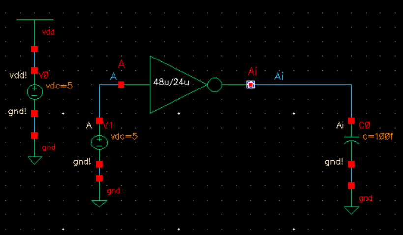
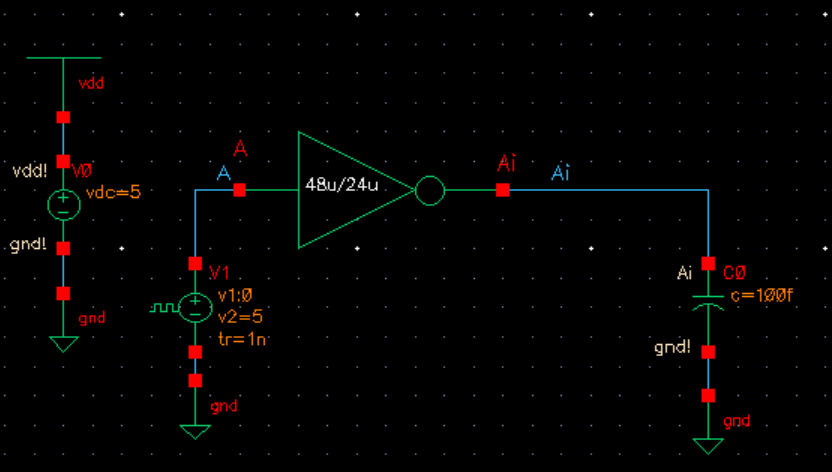
Simulation Schematics and Sims:
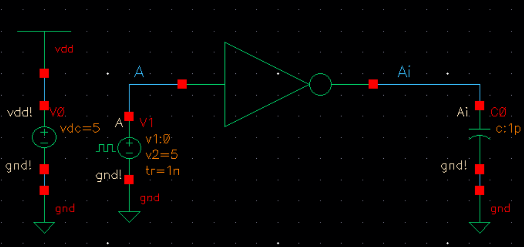
Schematic with capacitor we will be modifying its capacitance throughout:
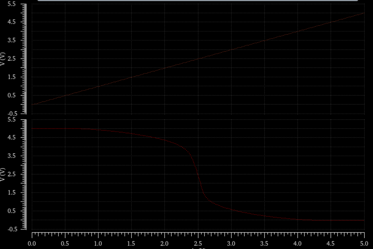
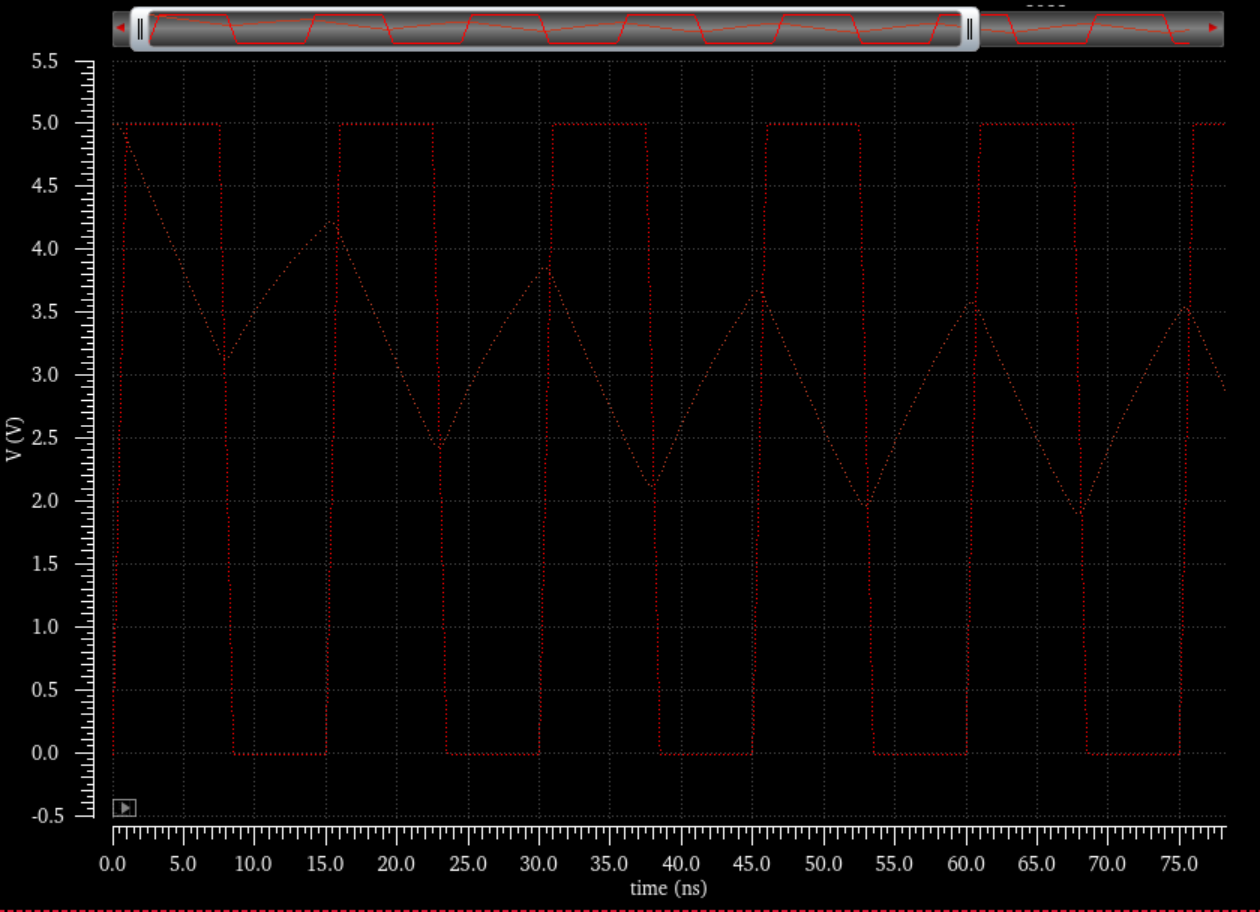
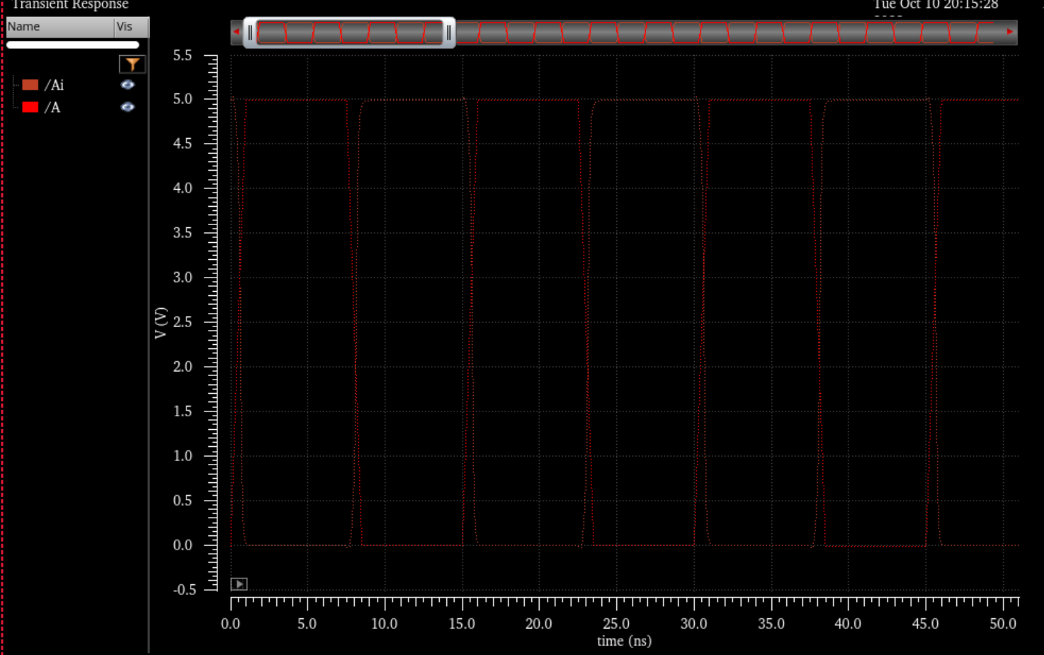
Specter Sims:
100fF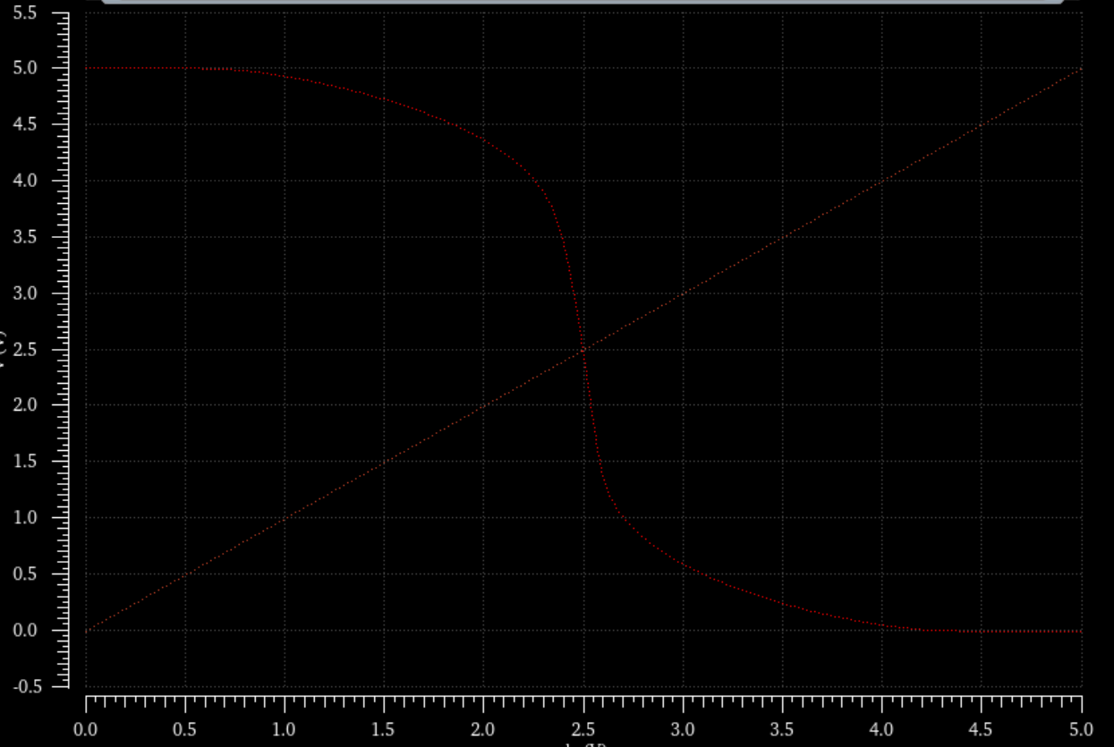
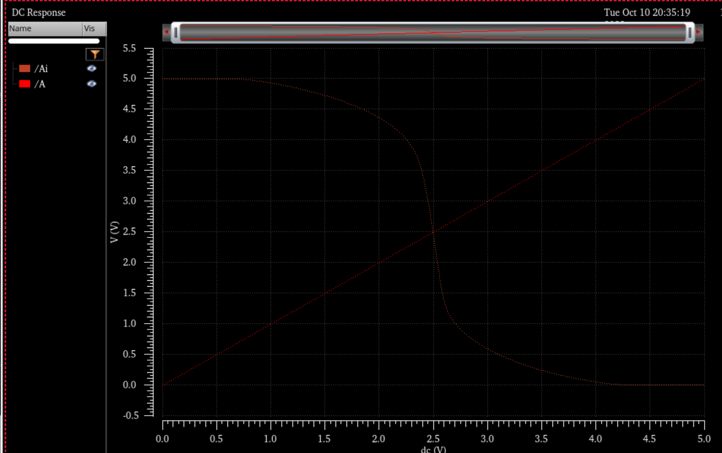
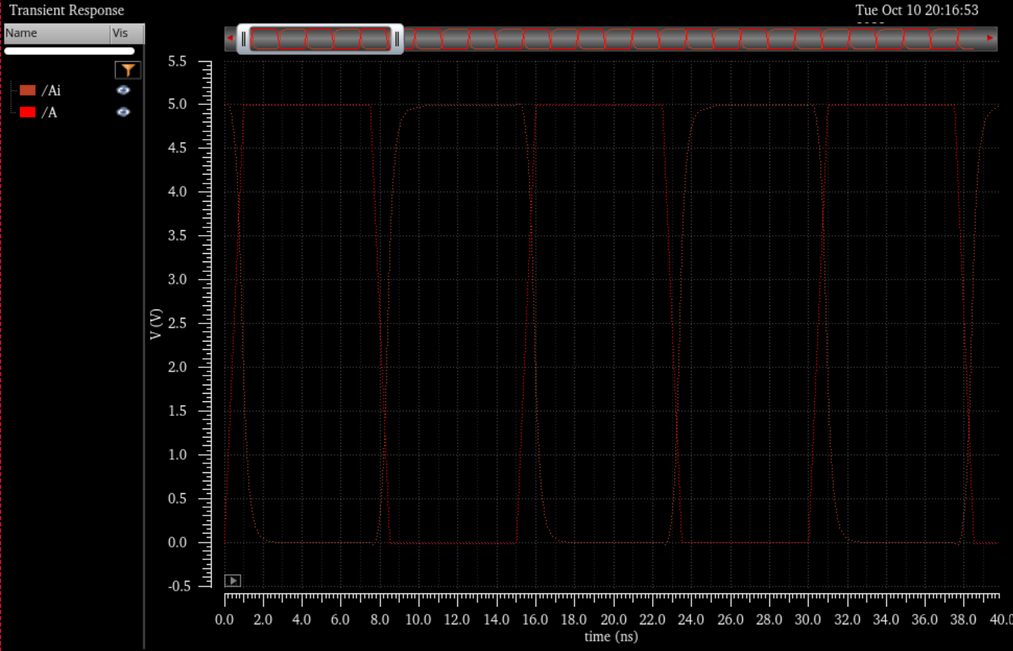
10pF Capacitor:
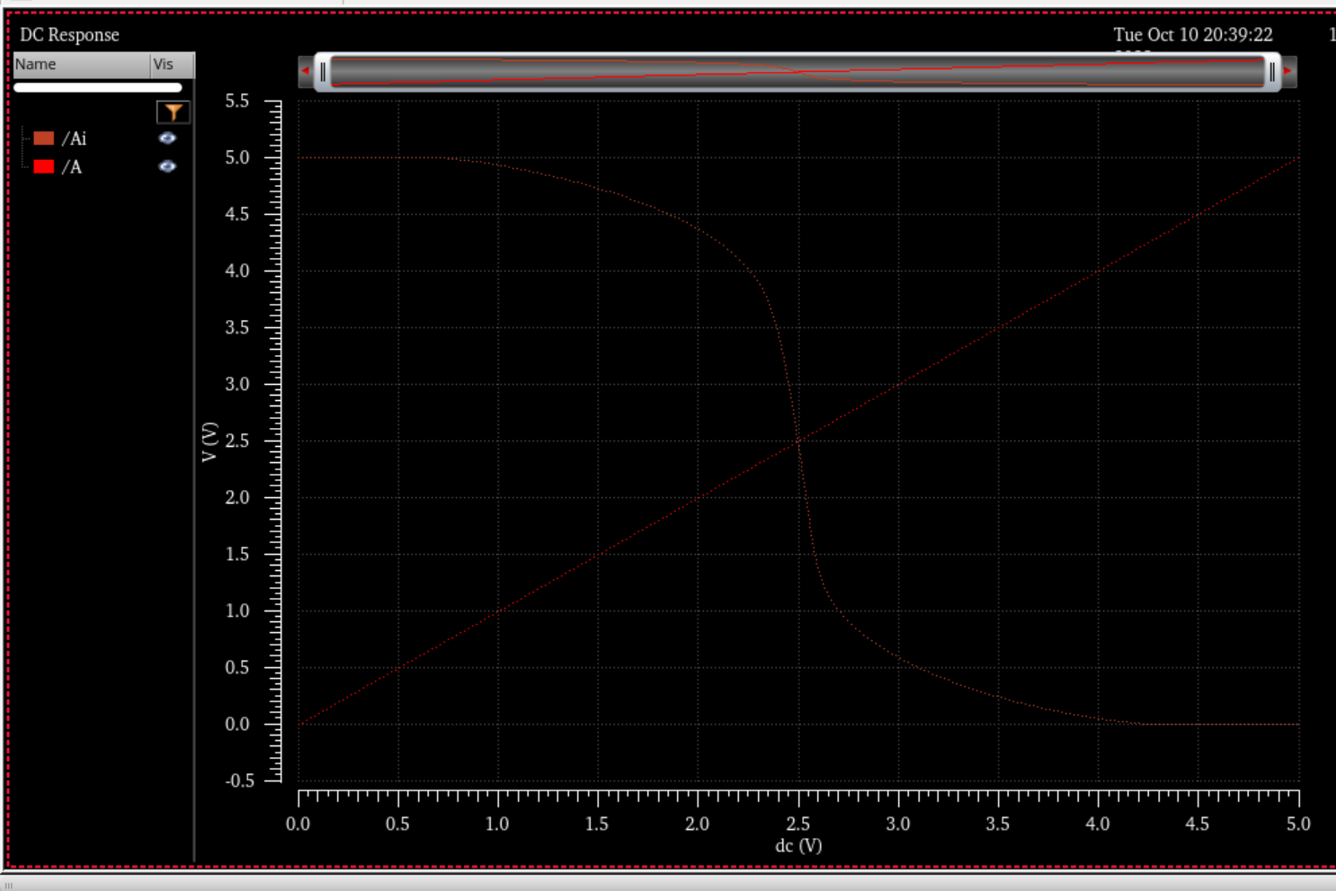
100pF:
Ultra Sim Simulations:
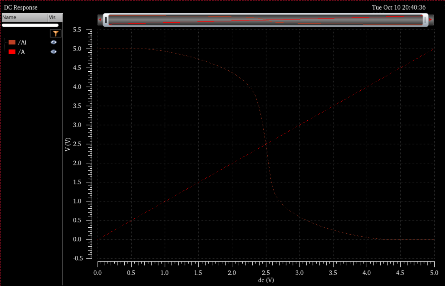
100fF Sim:
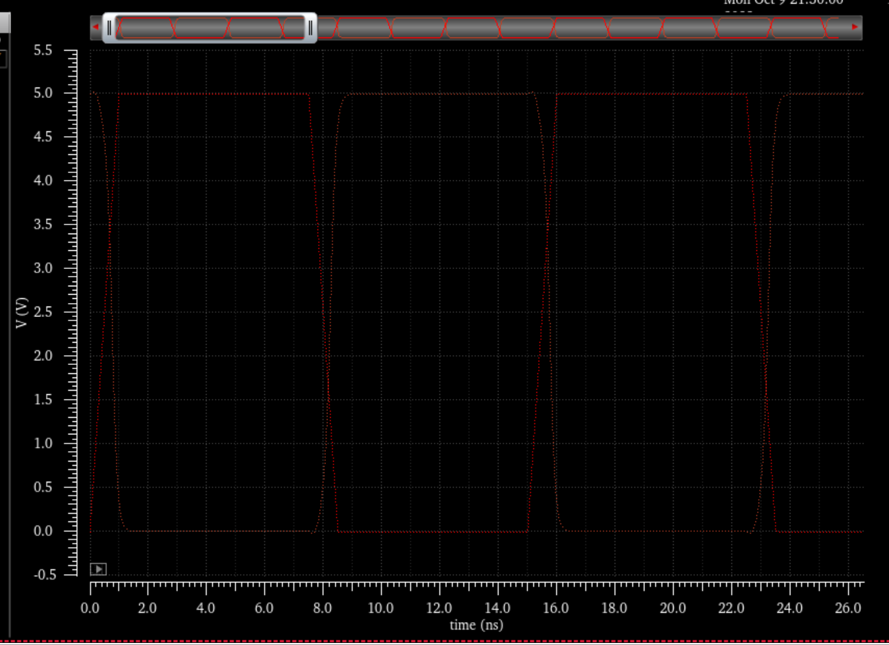
1pF Sim:
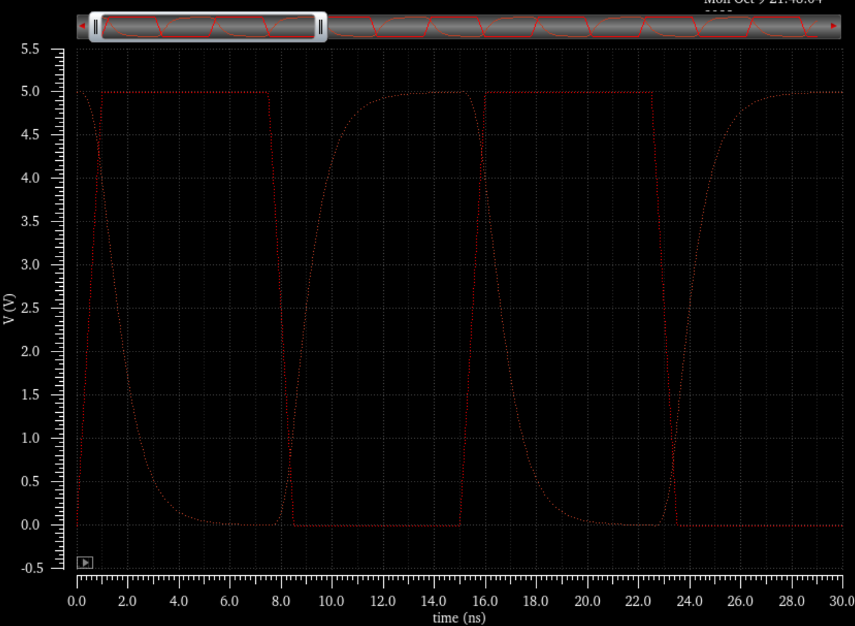
10pF Sim:
100pF Sim:
Schematic of NMOS-PMOS inverter:
Here is the symbol View:
Layout:
DRC:
Extracted:
LVS:
Simulation Schematics and Sims:
Schematic with capacitor we will be modifying its capacitance throughout for spectre sim:
100fF Simulation results: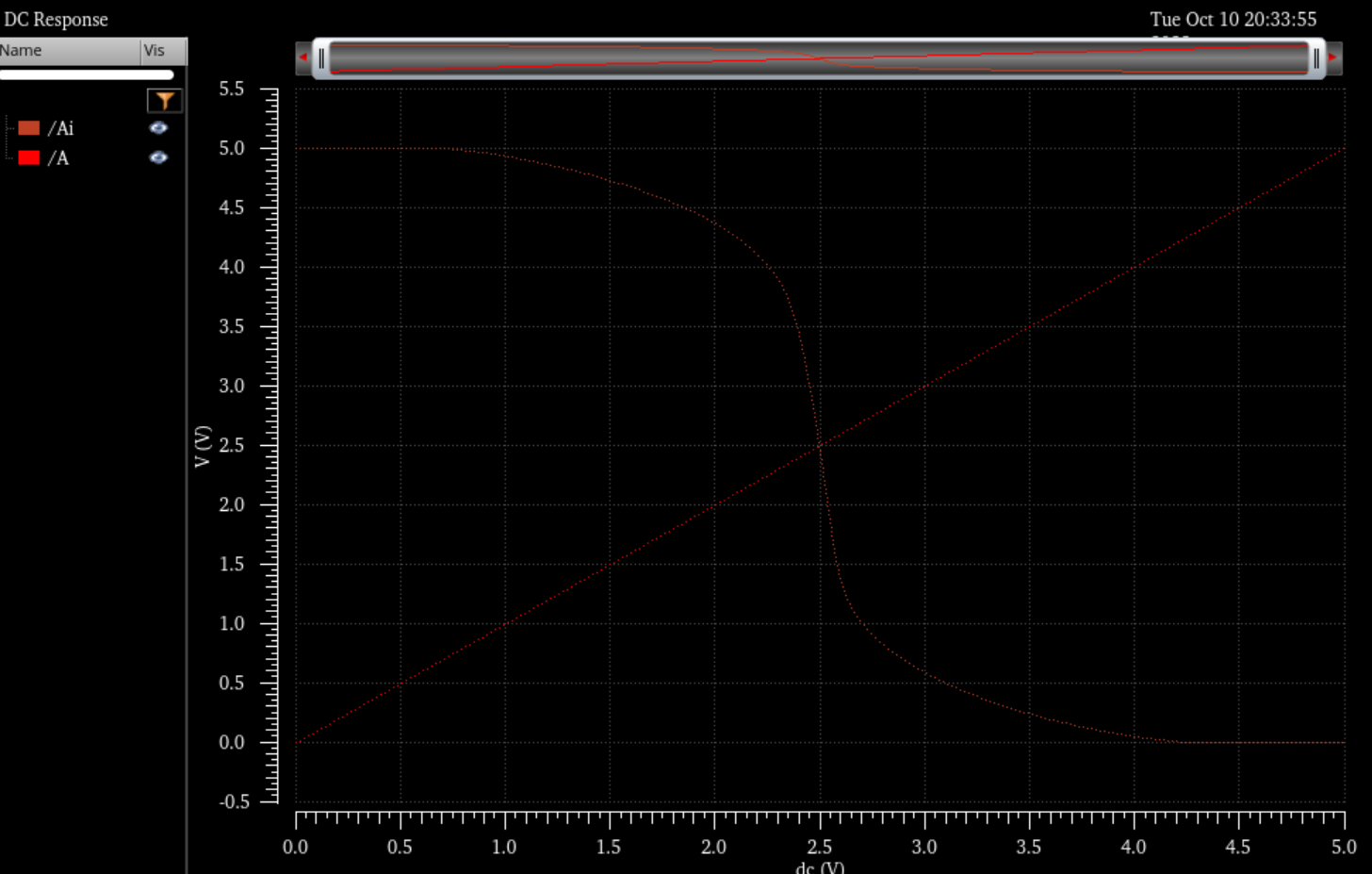
1pF Simulation:
10pF Simulation:
100pF Sim:
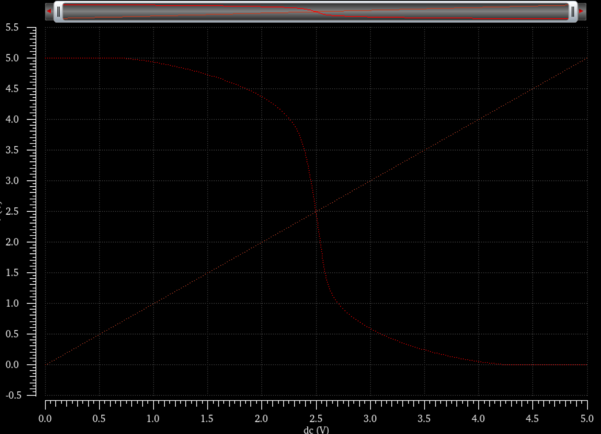
Ultra Sim Simulations:
Here is the schematic for US simulations in which the capacitance will be vairied.
100fF
1pF:
10pF: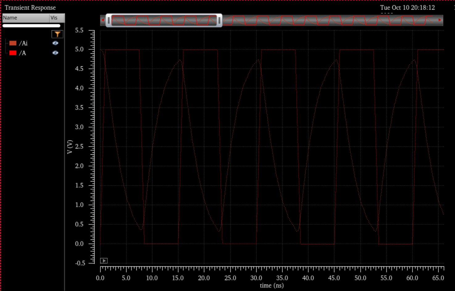
100pF:
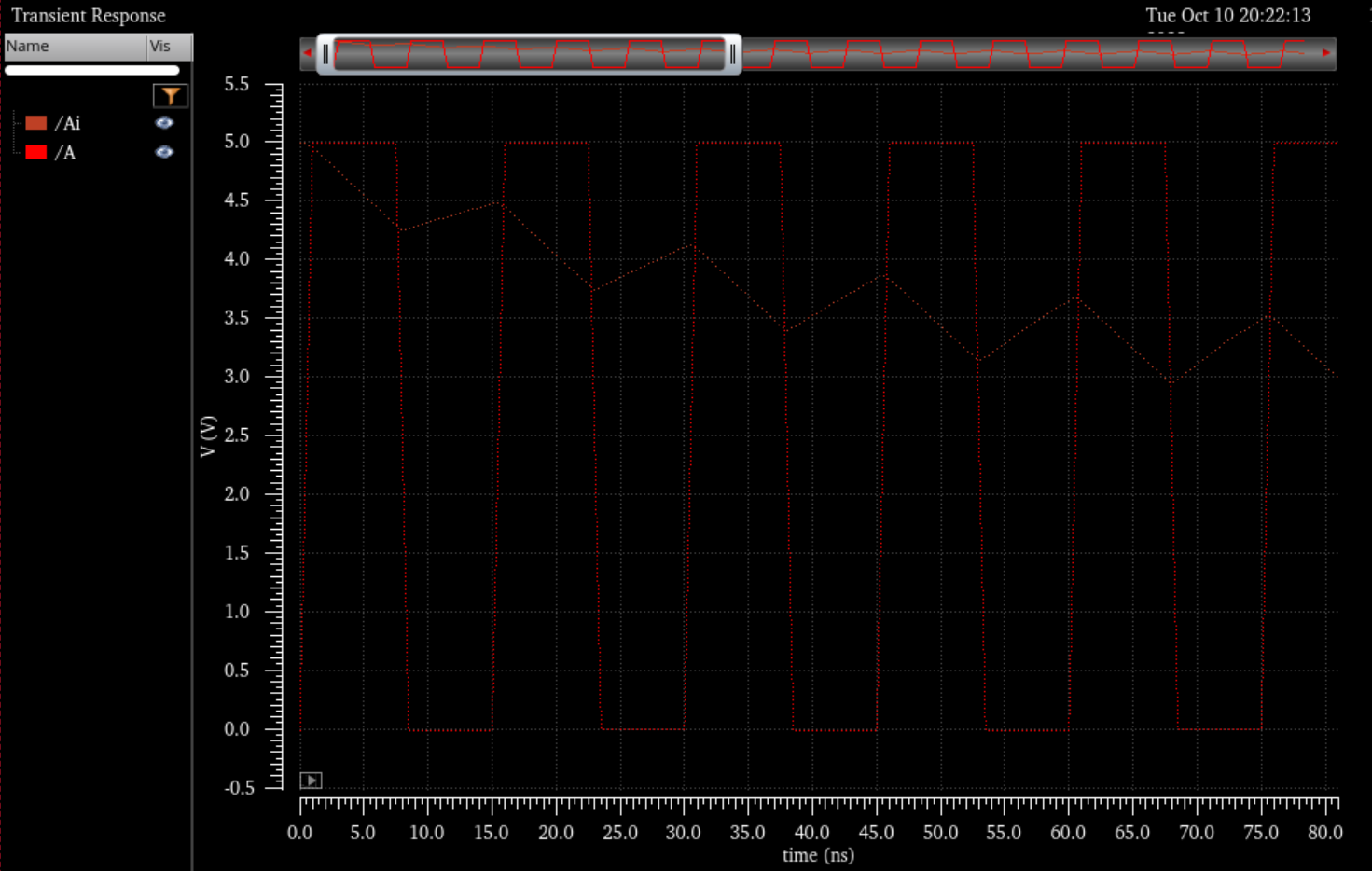
Conclusion:
The simulations imply that with the increase of the capacitance the transition slows down which follows the RC Circuit calculation which also explains why the larger is transitioning faster because the resistance is less and the smaller one transitioning slower because the resistance is more.
Download : lab5_ap.zip