Lab 2 - ECE 421L
Download
Lab2.zip
type:
then:
Run the sim (Launch the ADE, Session -> Load State -> Cellview -> OK, press the green start button)
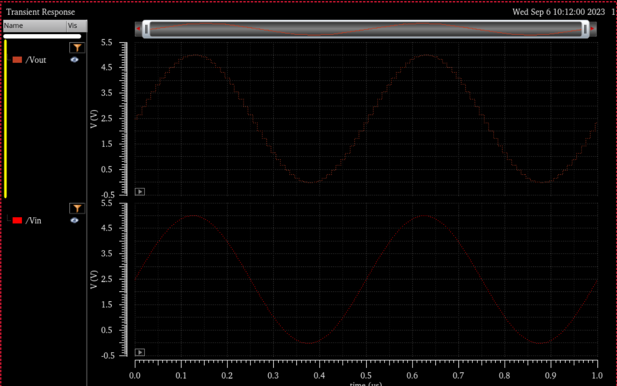
Vin is a AC wave that gets converted to a Digital 10 bit value with the ADC in relation to the 5v which divides the 5v to 1048 different possible digital values in which each bit is b[0] to b[9] that gets sent to the DAC which outputs the binary value to analogue but since it is split up to 255 discrete possibilites there will be bumps in the digital wave.
Lab 2 Report:
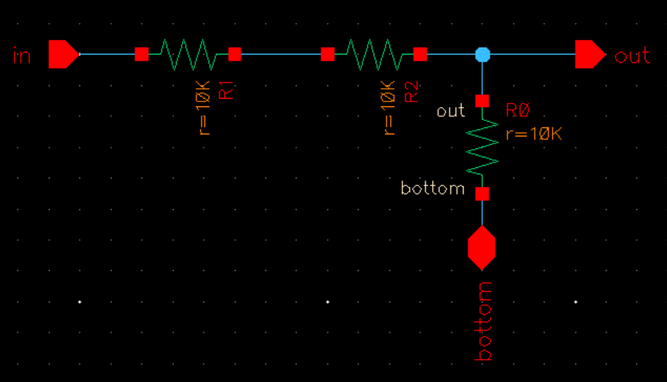
Here is a 10k n-well resister I created and that will be utilized in this lab.

We
then go to create -> Cellview -> From_Cellview...
Here is how the symbol is set
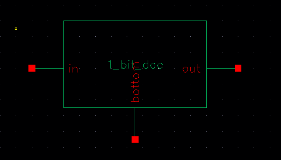
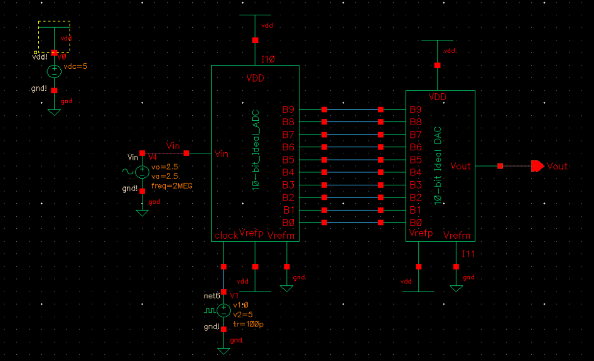
Combining this we can make a 10 bit dac as seen below
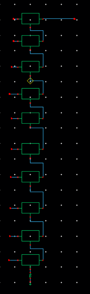
Now we can create the symbol again for the 10-bit dac
Delay Calculation:
Here is a sim
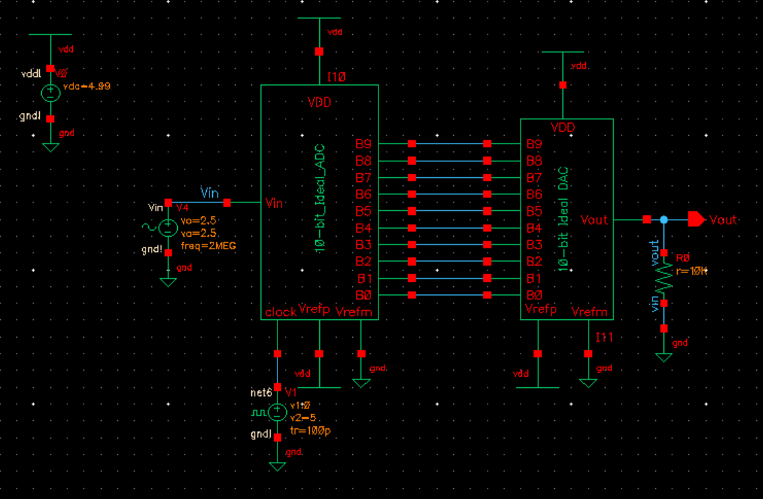
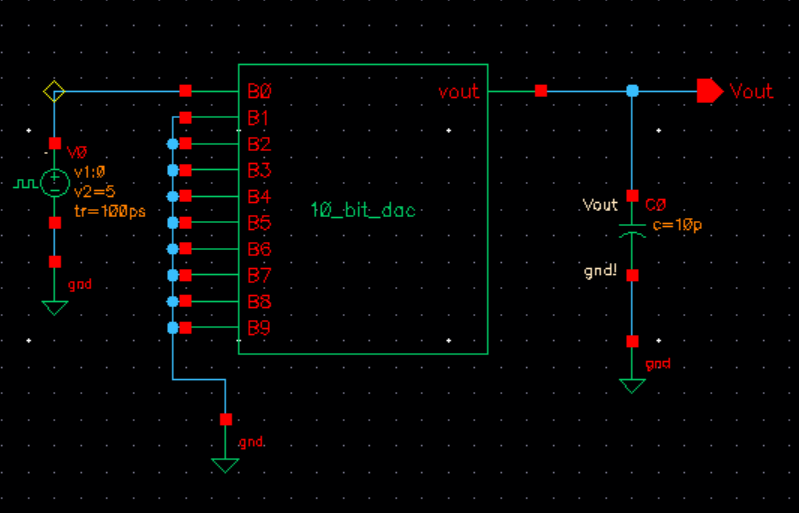
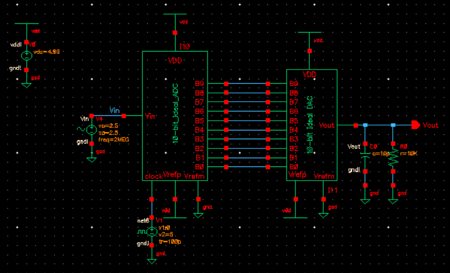
Here is the idea DAC added to the adc, the added 10K resister matches the internal 10k resistance of the dac which creates a voltage divider and will decrease the output voltage by half.
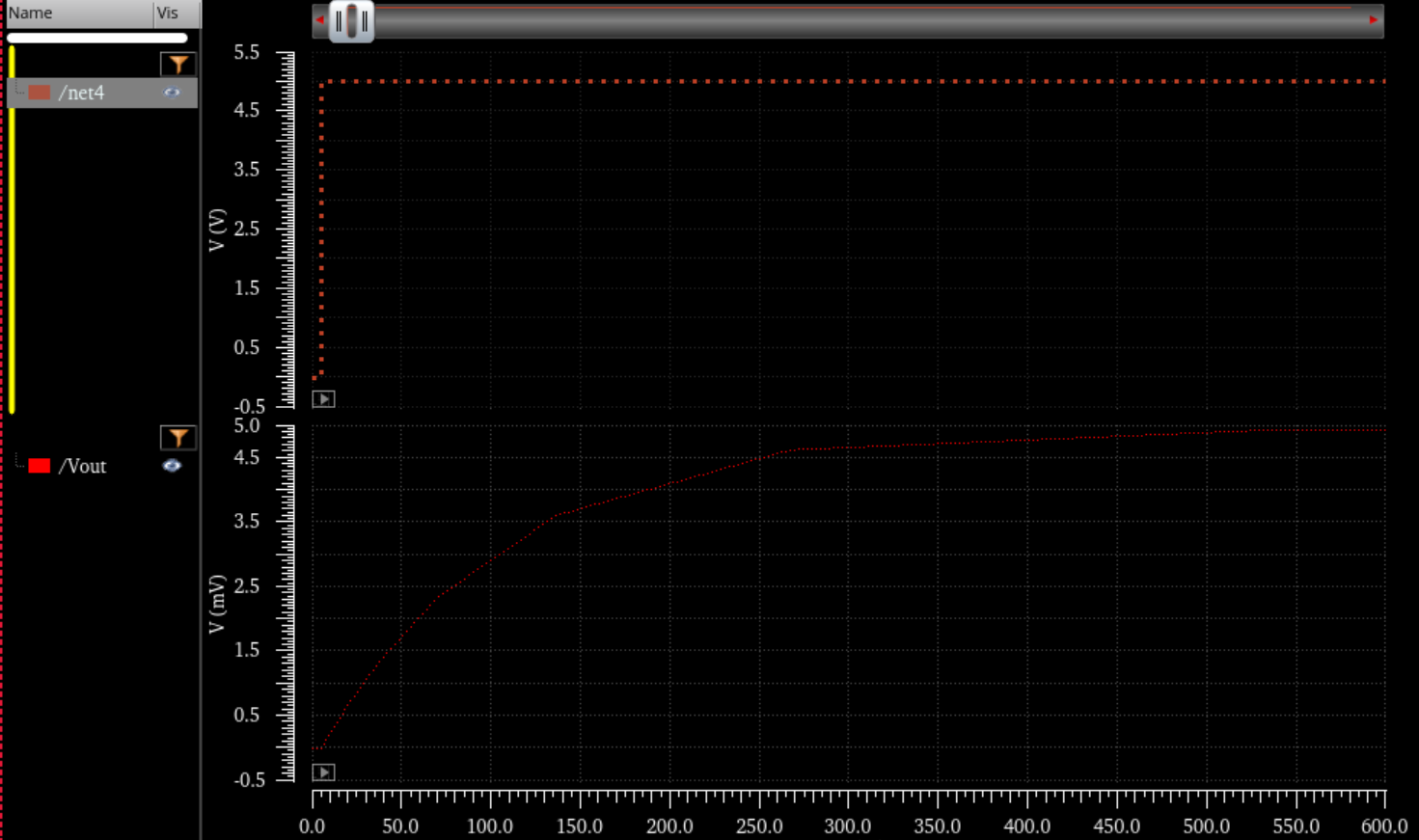
Here is the simulation: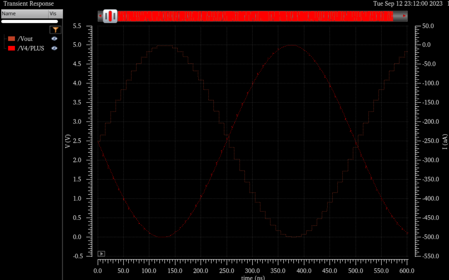
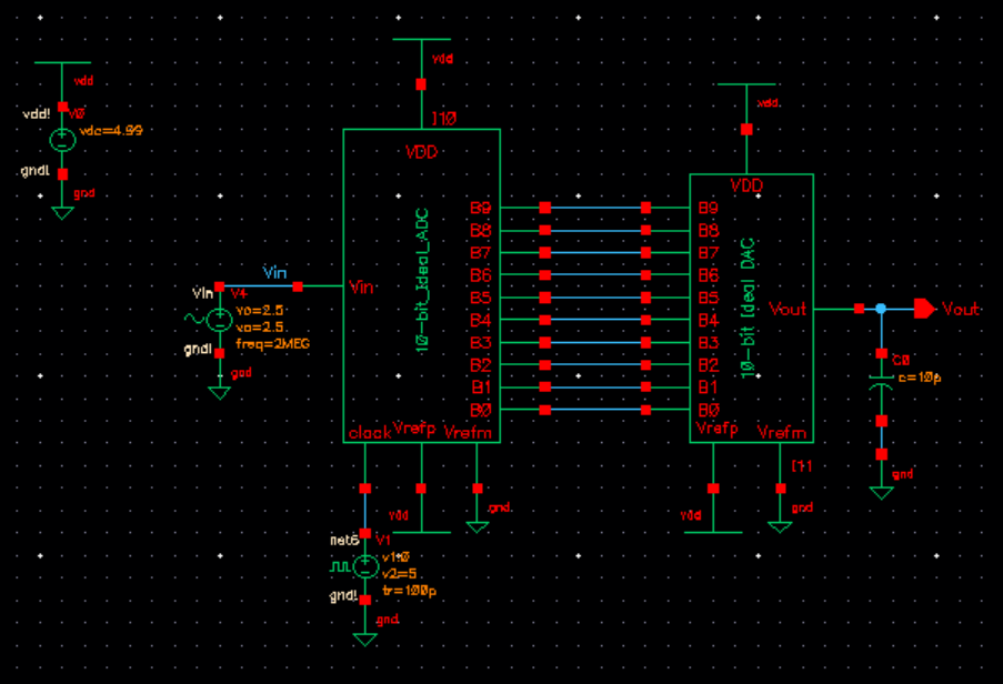
Here is the adc-dac with the 10pf capacitor which creats a delay in vout, decreases the output and smooths it out.:
With
the resister and the capacitor which decreases the output even further.
Here
is the simulation to back it up:
Backing Up My Work:
Zip up work every 20-30min and email it to myself