Lab 01 - EE 421L Fall 2023
Authored
by
Baylee Perera; pererb1@unlv.nevada.edu
9/6/23
Lab
description:
This
lab covers how to use html along with the proper formatting of the lab
reports that we will put together throughout the course of this class.
To prove we know how to do this, step-by-step pictures will be included
below.
Prelab:
The prelab consisted of gaining acces to our CMOSedu accounts through Dr. Baker and learning how to edit our html file through KompoZer.
Lab Work:
This lab will be following along with the Cadence Tutorial 1. However, we will only be following it until the 25th image in the tutorial and then will be switching over to this website to guide us for the rest of the lab.
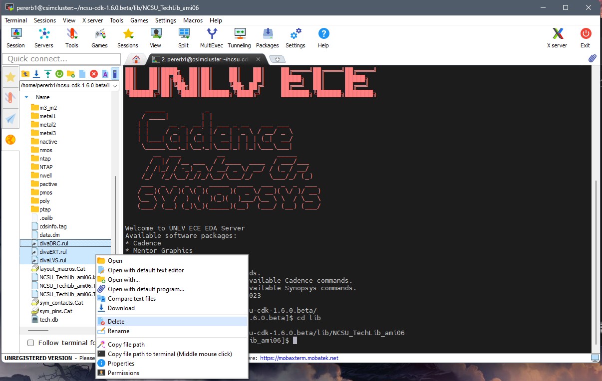
We
must first start off by removing the old diva files from our directory
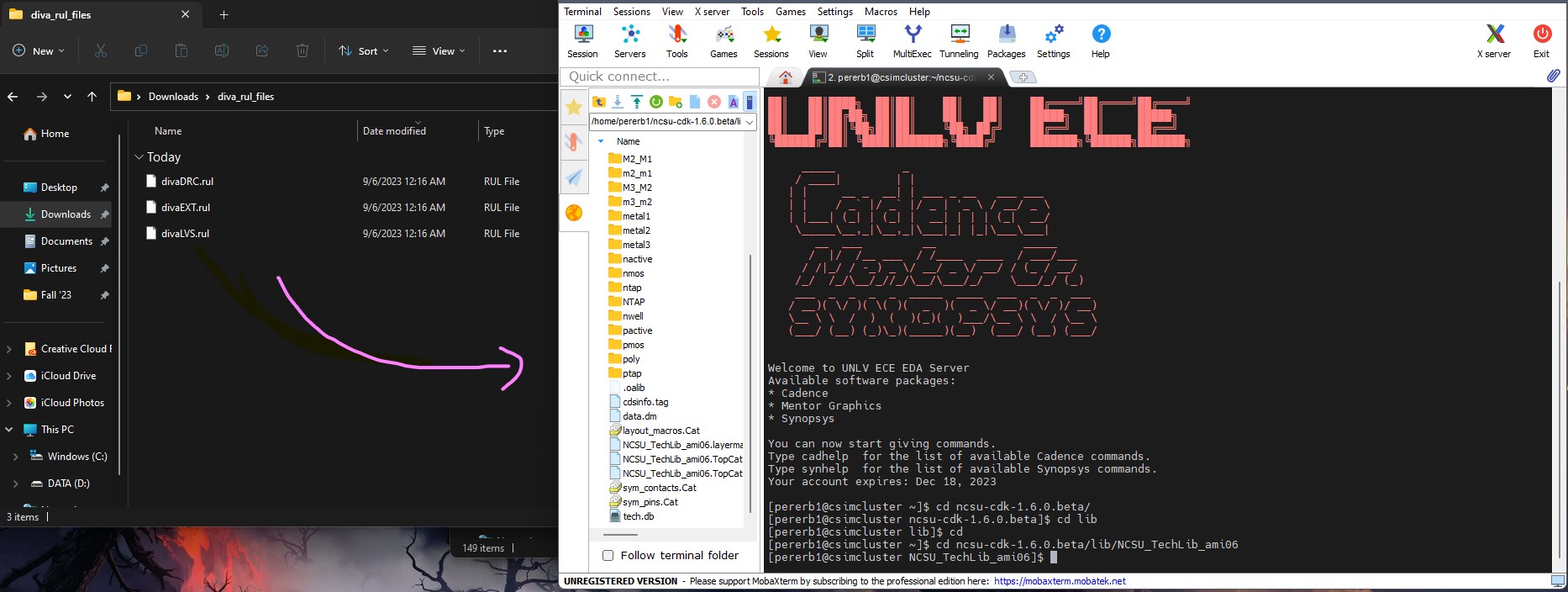
and substituting them in with the new files provided to us. We do this
do to a bug that is in the beta version.
Removing files:
Adding new files:
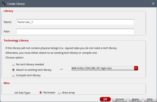
We will next be creating a new library inside of Cadence and attaching an existing tech library to it called AMI 0.60u C5N.
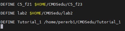
Once we have the new library created, we want to make sure that the libraries were defined in our cds.lib.
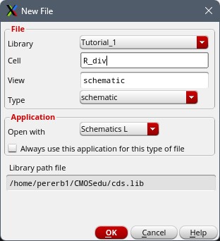
Next
we will be making a new cell view. You would do this by clicking on the
"Tutorial_1" library in the library manager. Followed the by File -> New -> Cell View.
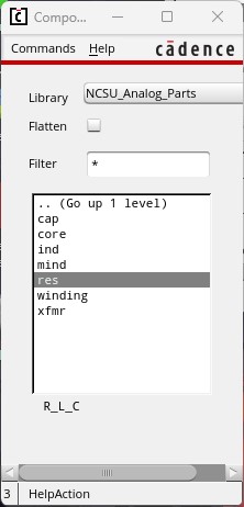
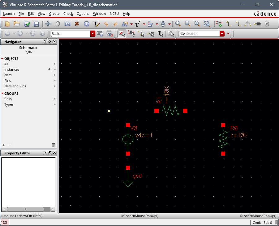
Once the new cell view has been made and opens, we will start by making two resistor components. We do this by pressing the Bindkey i (or use the menu at the top under the "create" tab). When the Instance window appears we will proceed with the following: Library -> NCSU_Analog_Parts -> R_L_C -> res. After
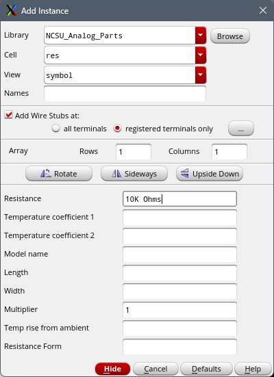
they have been selected, you will get a window that shows like below
and will need to change the resistor value to 10k Ohms.
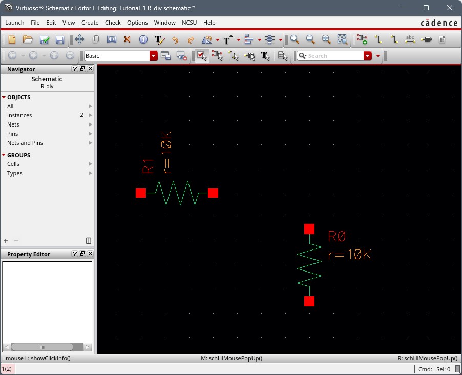
Proceed to hide the window and include the resistors into your schematic editor. Note: Bindkey F will fit the display window. Addition Bindkeys can be found here. You may click your mouse button to rotate the resitor or hit Bindkey R.
Pushing the 'esc' button wil close out of instance mode. If you later
need to change the value of the resistor, simply click on it and hit
Bindkey Q or Edit -> Properties -> Objects.
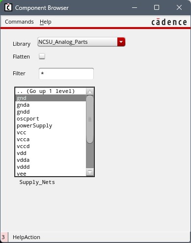
The next step will be adding a ground to our schematic. We will do this again by clicking I, selecting Supply_Nets and then gnd like shown below.
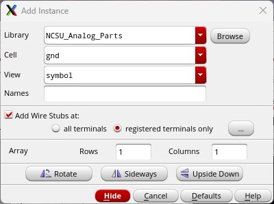
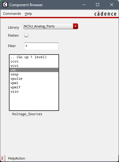
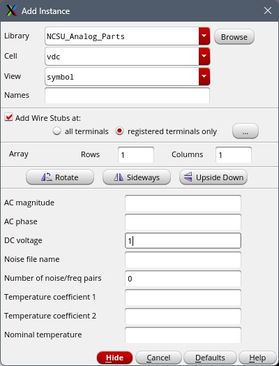
Add the ground symbol onto your schematic, followed by a voltage source set to 1-V DC.
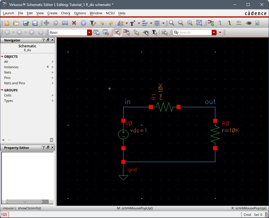
Next we will add wires by using the Bindkey W or going up to the menu. It is useful to include signal names to your wires using Bindkey l (which is a lowercase L).
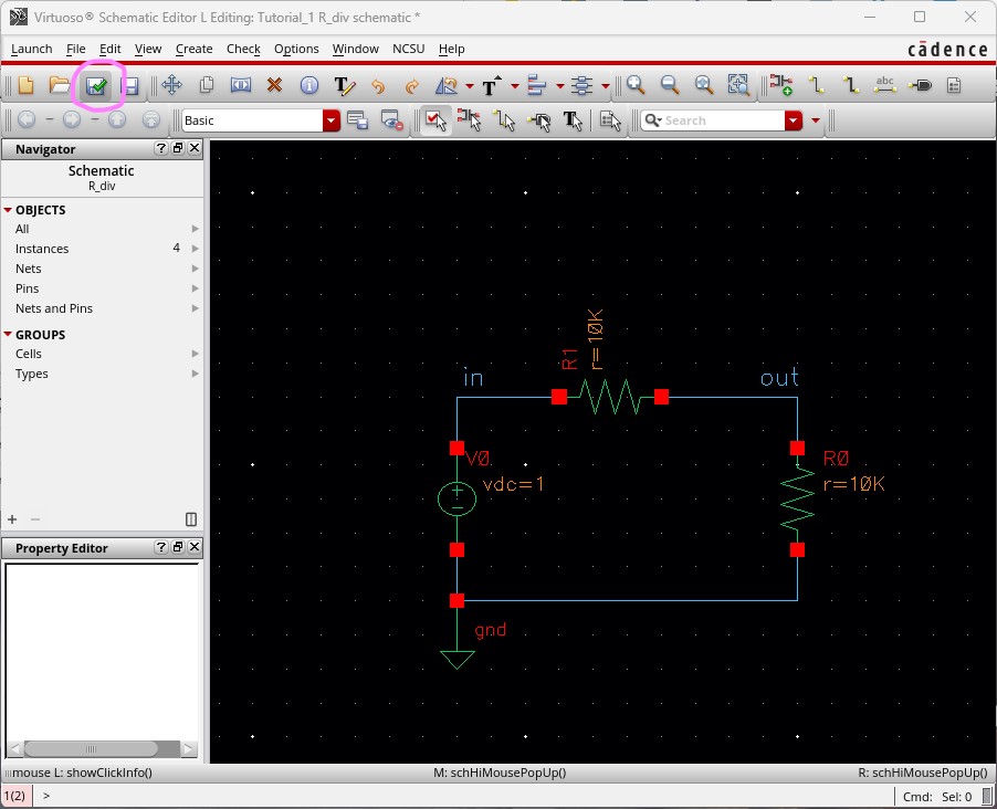
We're now ready to start the simulation of our circuit. But first we must make sure to Check and Save our work.
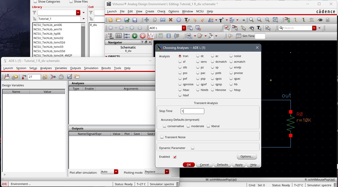
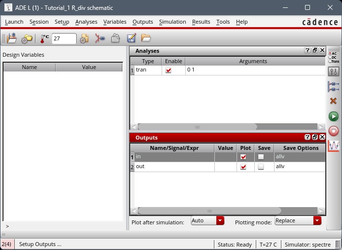
We'll now start the simulation process by first pressing Launch -> ADE L. ALWAYS make sure that your circuit is running in spectre. You can do this by Setup -> Simulator/Directory/Host, make sure to change it if it is not. Next proceed to Analysis -> Choose -> tran. Change your stop time to 1 second and that you also have enabled box checked as well.
We now need to know what signals it is we want to plot. We'll do this by selecting Outputs -> To Be Plotted -> Select On Schematic. You will be selecting "in" and "out" on the schematic which will then appear as shown:
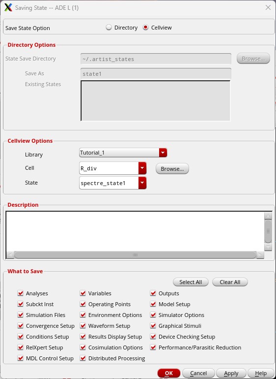
Before
we run the simulations, we'll want to save all this information so we
don't have to go through this long process again. Going back to the ADE
L window, use the menu by selecting Session -> Save State -> Select 'Cell View' -> OK.
In the future, we will instead follow Session -> Load State -> Select 'Cell View' -> OK.
We will now press the green button to run the simulation and obtain our results.
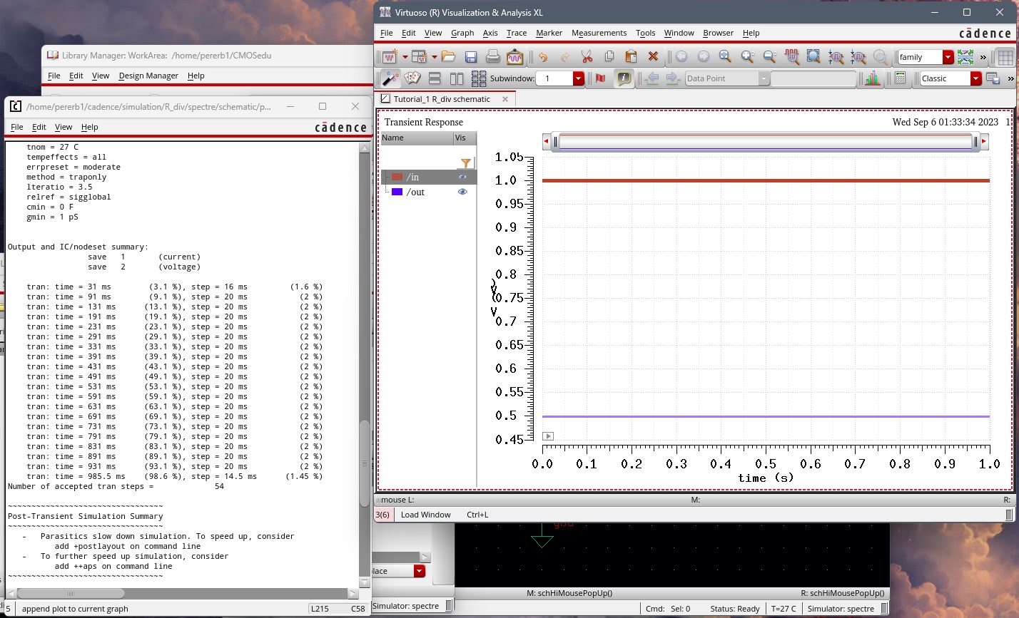
To
add some customization and make it easier for viewing, if you right
click on the trace name, then select trace properties, you can change
the line to be solid instead of dotted, along with changing to a thick
line. Which is how I have my picture shown above.
While working on my website, I did zip my folder and sent it to myself as a backup incase something went amiss.

Return to previous labs