Lab 3 - ECE 421L Fall 2023
Pre-lab:
I backed up my files from the lab and course.
The prelab wants us to finish Tutorial 1.
We took the schemaic that we worked on previously, and added an input pin and output pin.
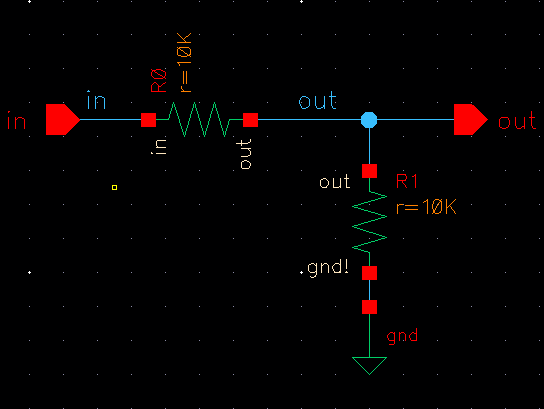
Still going through the tutorial we then create a 10k ohm n-well resistor. The turtorial wanted the
Length to be 56.1 and thewidth to be 4.5. Following this step we add ntap on each side of the resistor.
Then go to the metal1 layer of the layout and selecte Create -> Pin, and label L and R on each ntap.
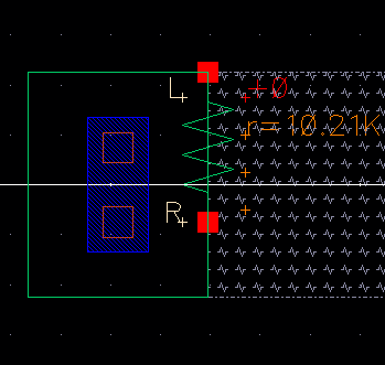
Following this you would DRC the 10k n-well and extract the layout. Once extracted you should see that
10.21k ohms is the value of the resistor.
Then we make and a R_n_well_10k layout, and check with DRC that there are no errors. Following this
we and in, out, gnd pins on metal1 layer. Then extract the layout and select Verify -> LVS and hopefully
it will match.
Lab:
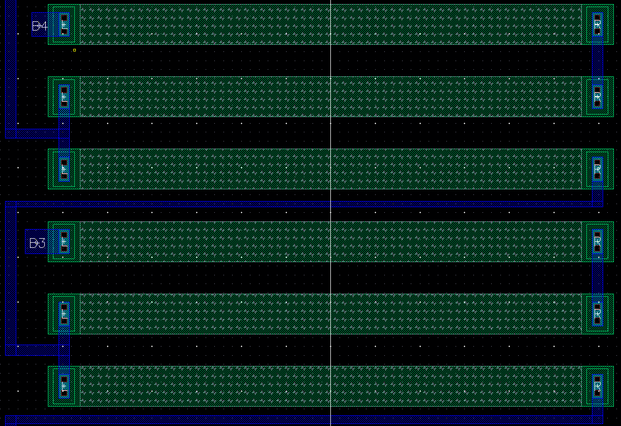
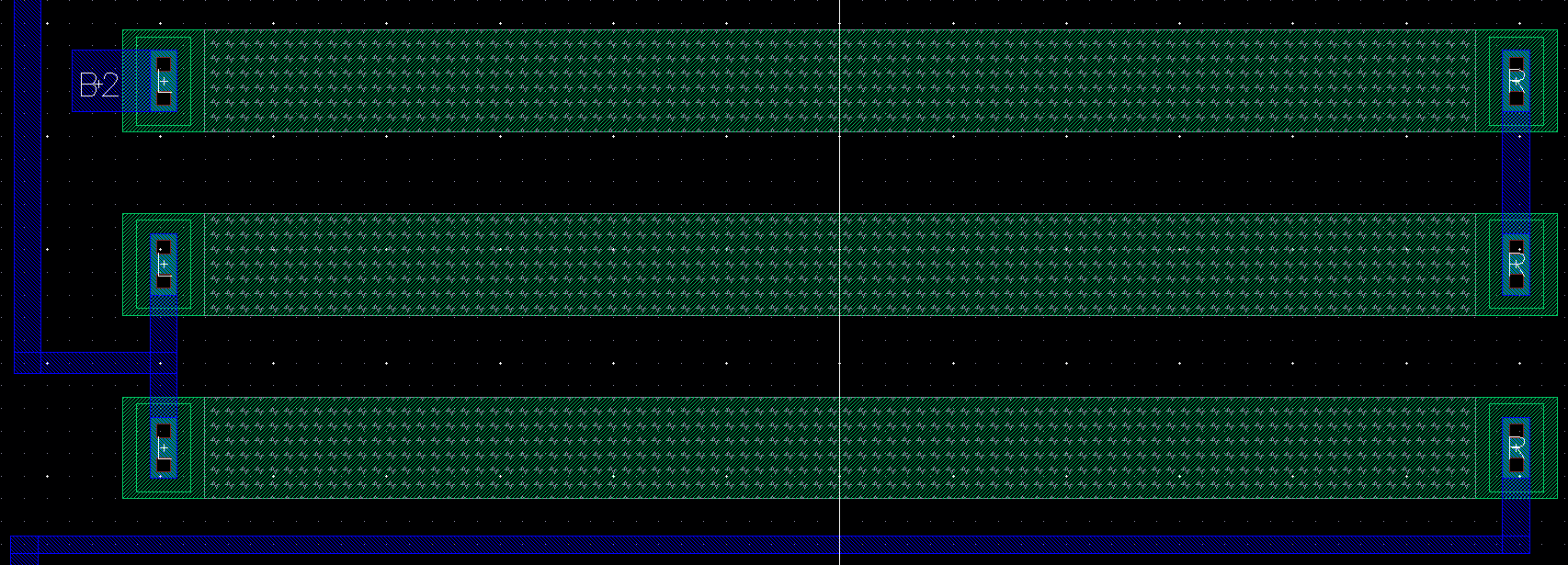
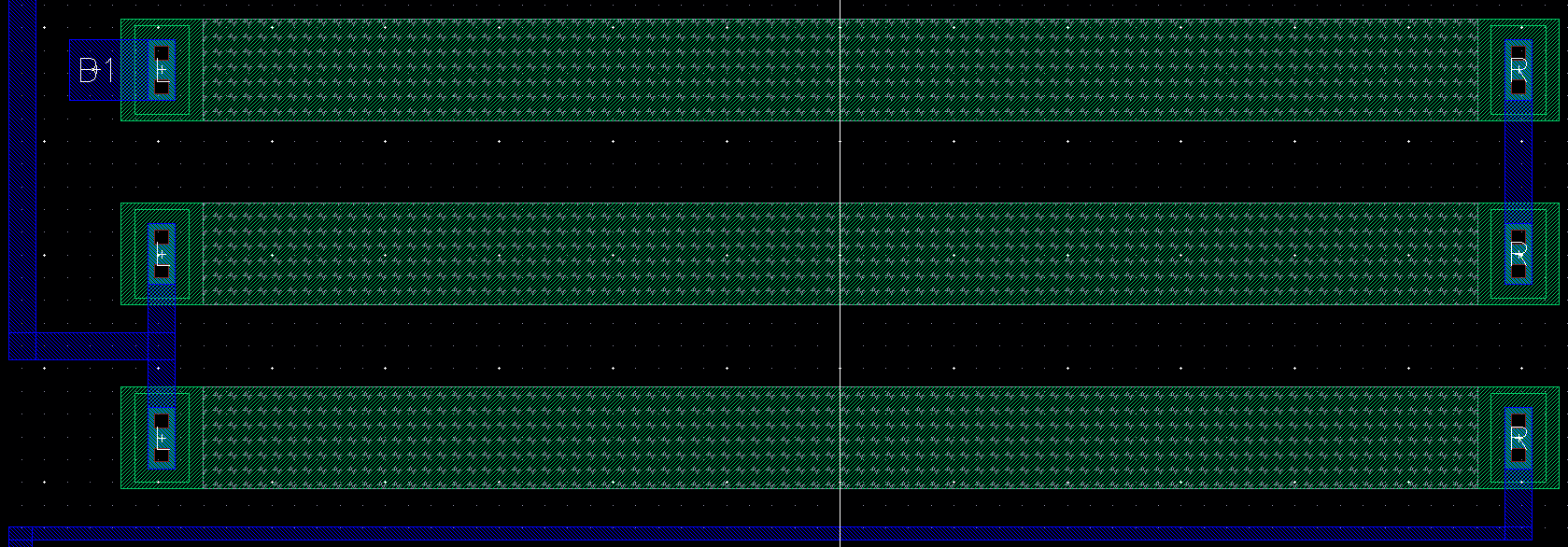
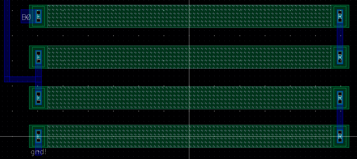
In this lab, I am to create a layout of the 10-bit DAC.
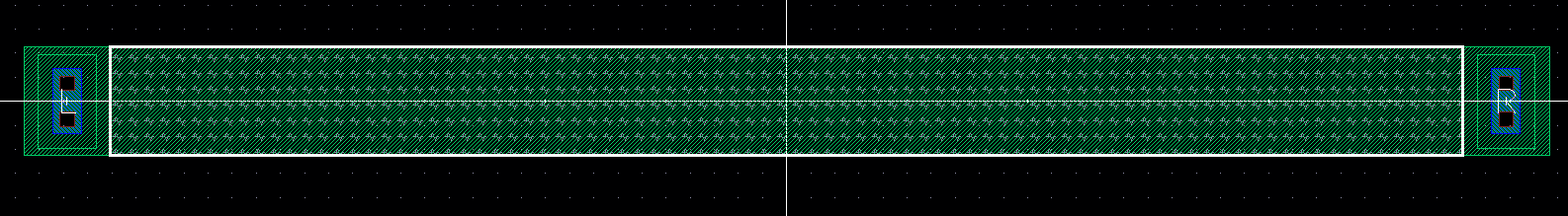
The first thing to do is create a 10k ohm resistor.The dimensions for the resistor is found with the
equation Rd = Rsquare * (L/W) . The length I went with is 56.1 and width is 4.5. I took the 10k ohm
resistor and put them with a layout.
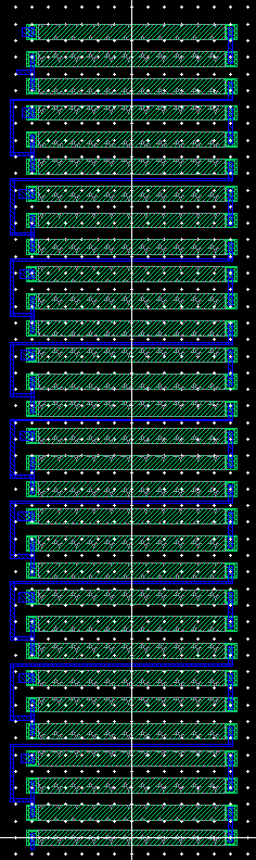
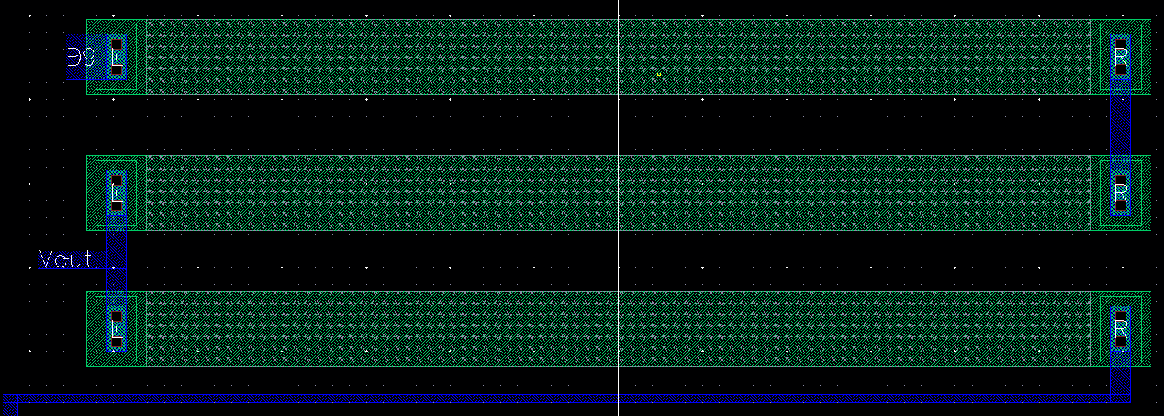
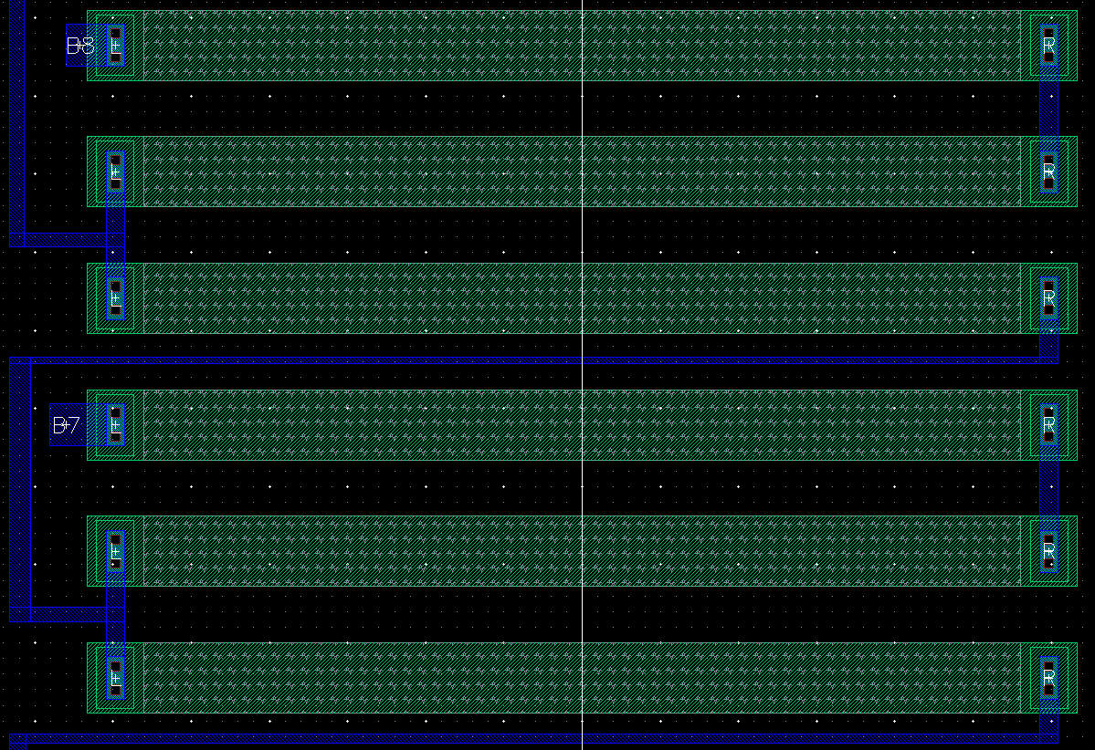
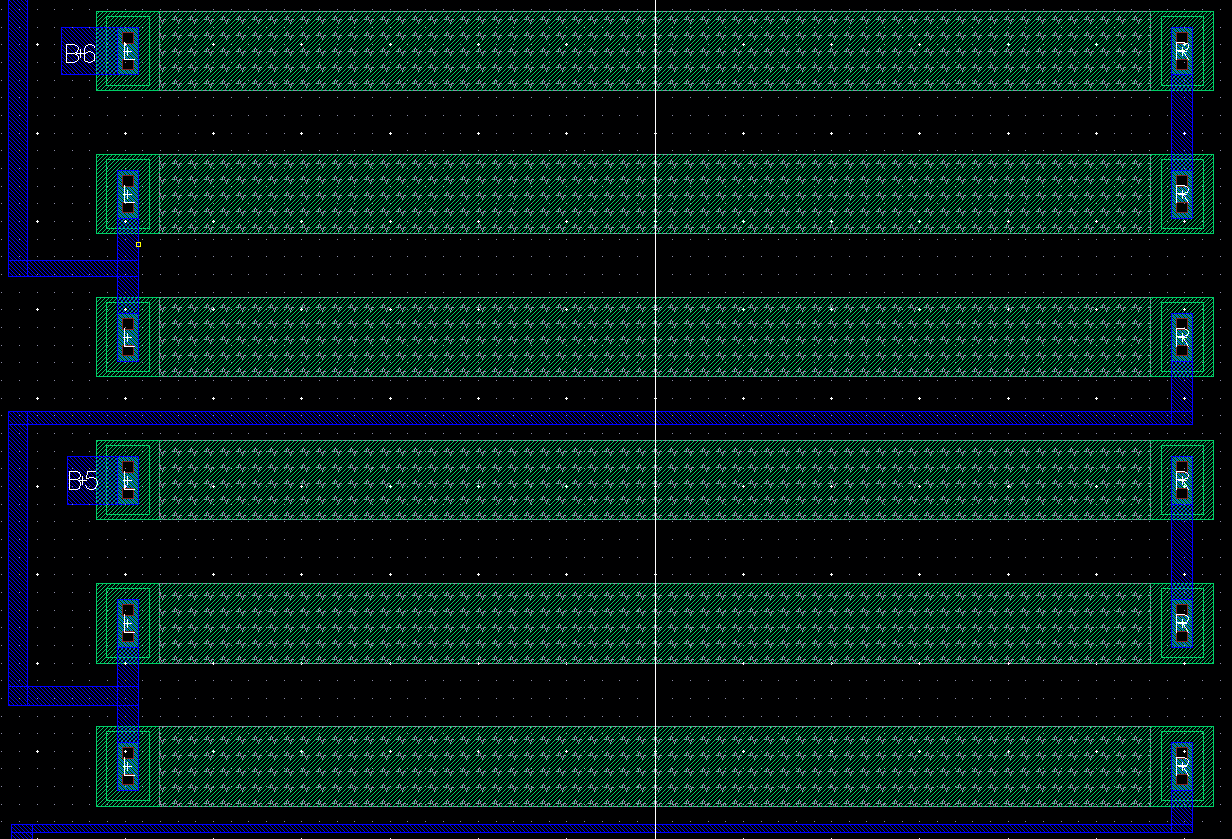
Above we can see the whole layout of the 10-bit DAC. While below we can see a more zoomed layout.
Next, I DRC the layout to check for errors,, to hopefully get none. The I would LVS the layout with the schematic to make sure that they match.
Return to EE 421L Labs