Lab 5 - ECE 421L
Authored by Josue Magana Quezada
Email: maganaqu@unlv.nevada.edu
10/11/2023
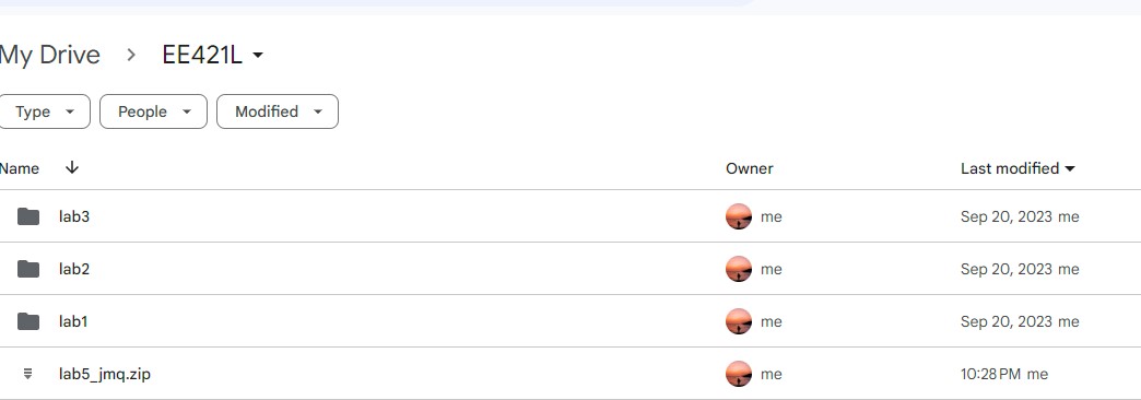
ZIP FILE!!
here

Prelab
For this prelab we will follow the same process of backing up our previous lab work as well as following Tutorial 3 that
is basically focused on using inverter with NMOS and PMOS. We will use LVS to double check if they match.
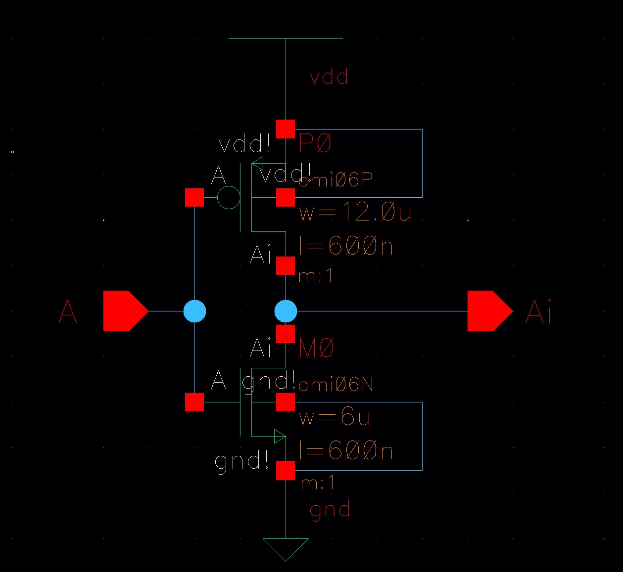
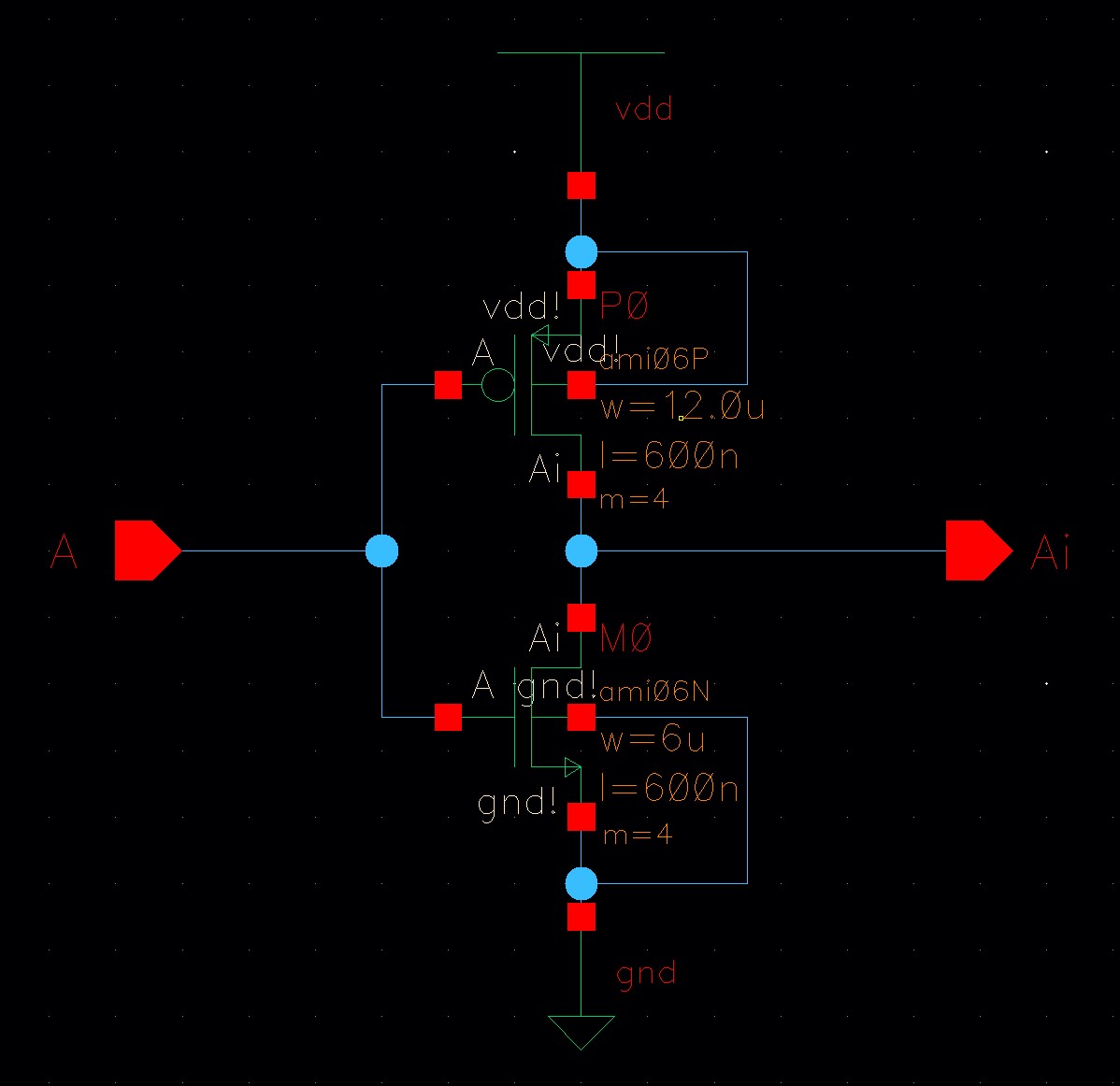
Here is the Schematic of the inverter with LVS verification

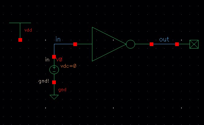
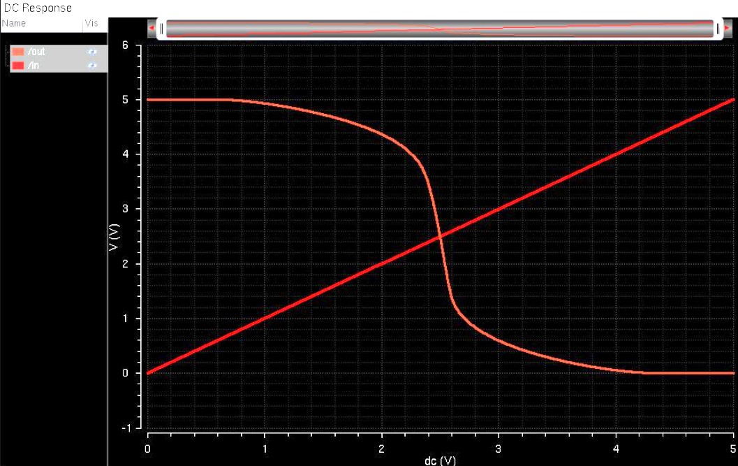
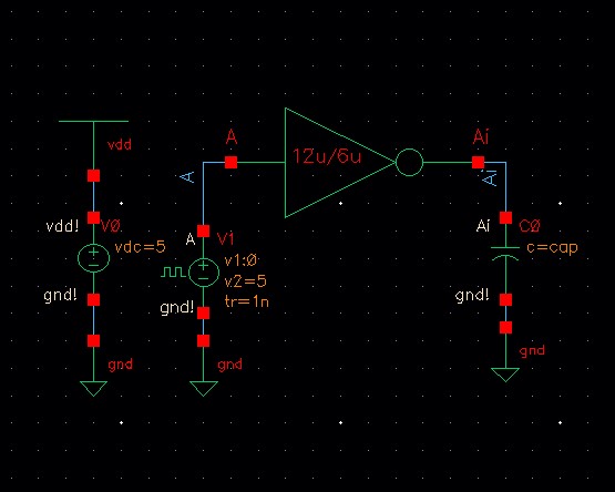
Here the schematic of the inverter and the output of the inverter compared with the input
Lab Work
The
1st part of this lab work is basically from this prelab. Like here,
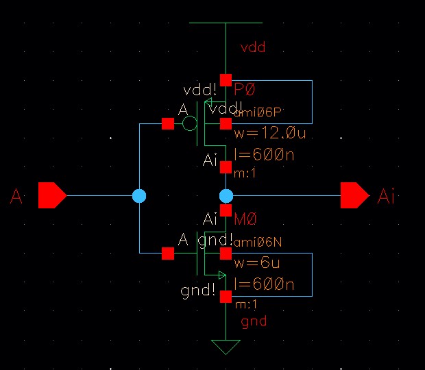
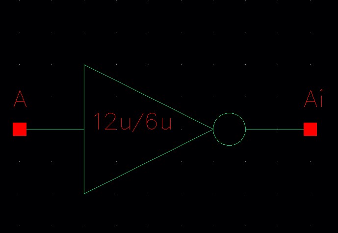
we'll be able to see the schematic, symbol of the 12u/6u inverter
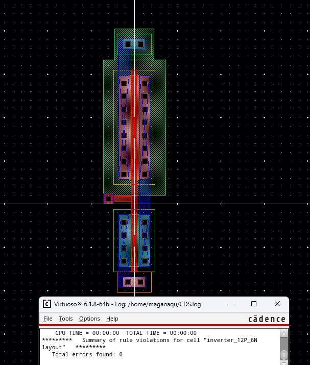
Layout with DRC verification
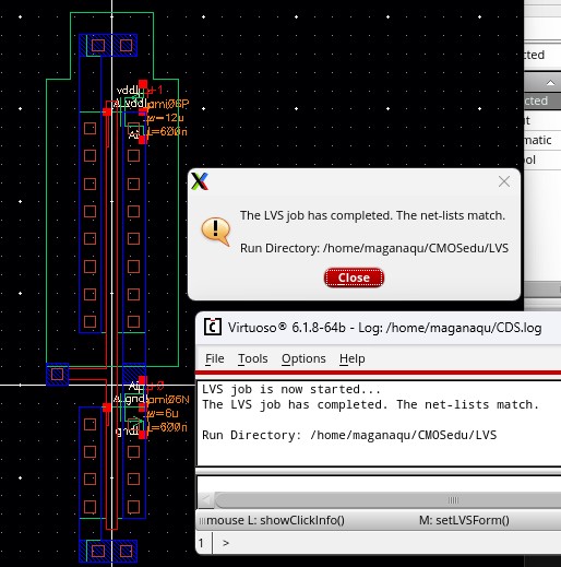
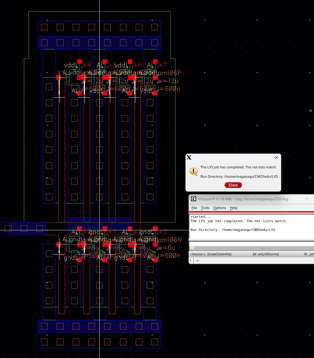
Extracted with LVS...
Now
that we have that, the next step is making an inverter, but we can't
make the transistors as big as we want. So, we're going to use a trick
by using more
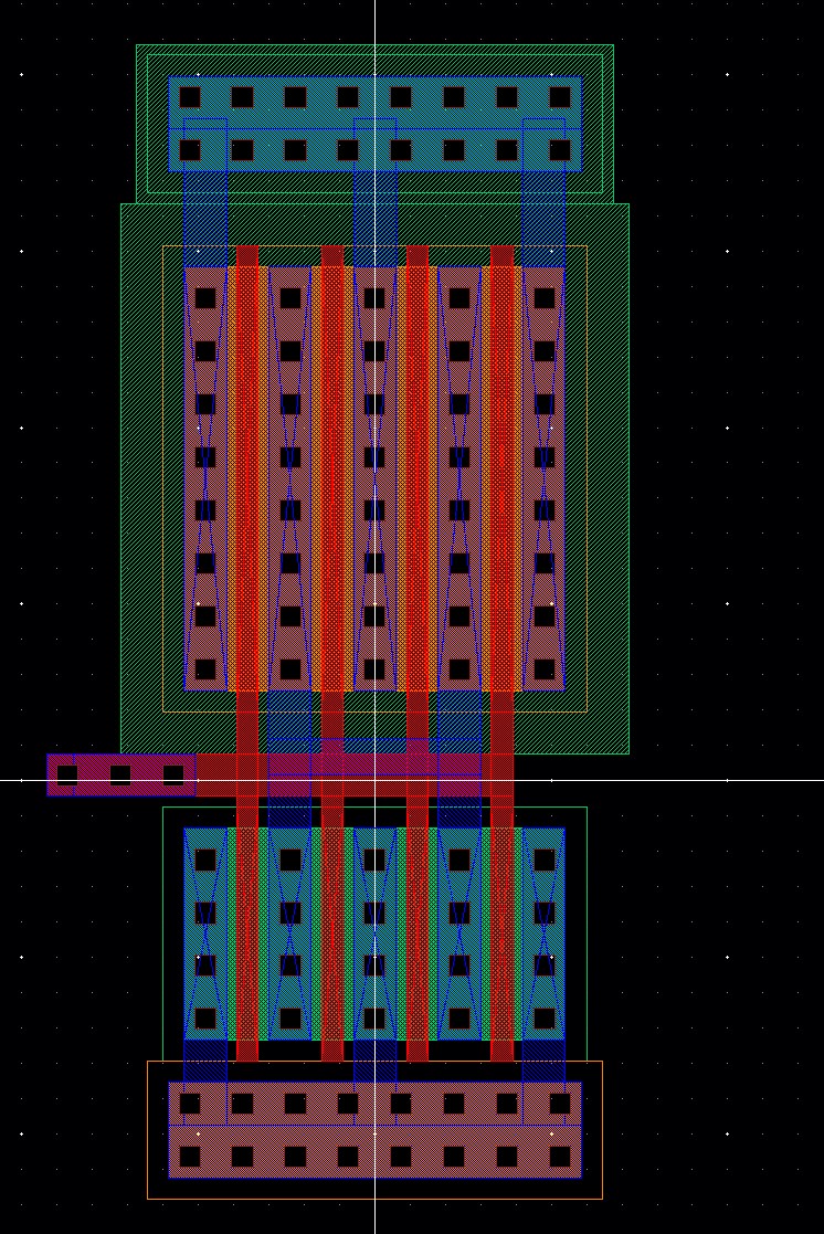
transistors to make it work like it's the right size, like here We
increase the multiplier for both the PMOS and NMOS transistors to 4
because 12u multiplied by
4
equals 48u, and 6u multiplied by 4 equals 24u. This might need some
changes in how we wire things on the chip, but the main idea remains.
We still have to create
a schematic, symbol, layout, and extracted view, just like before.
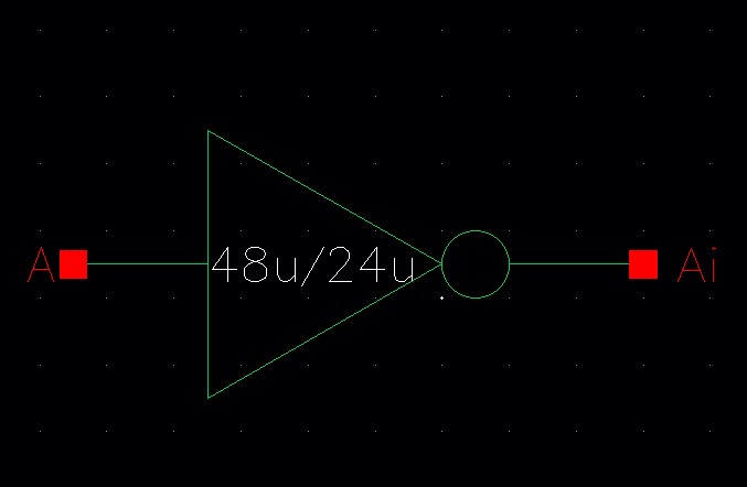
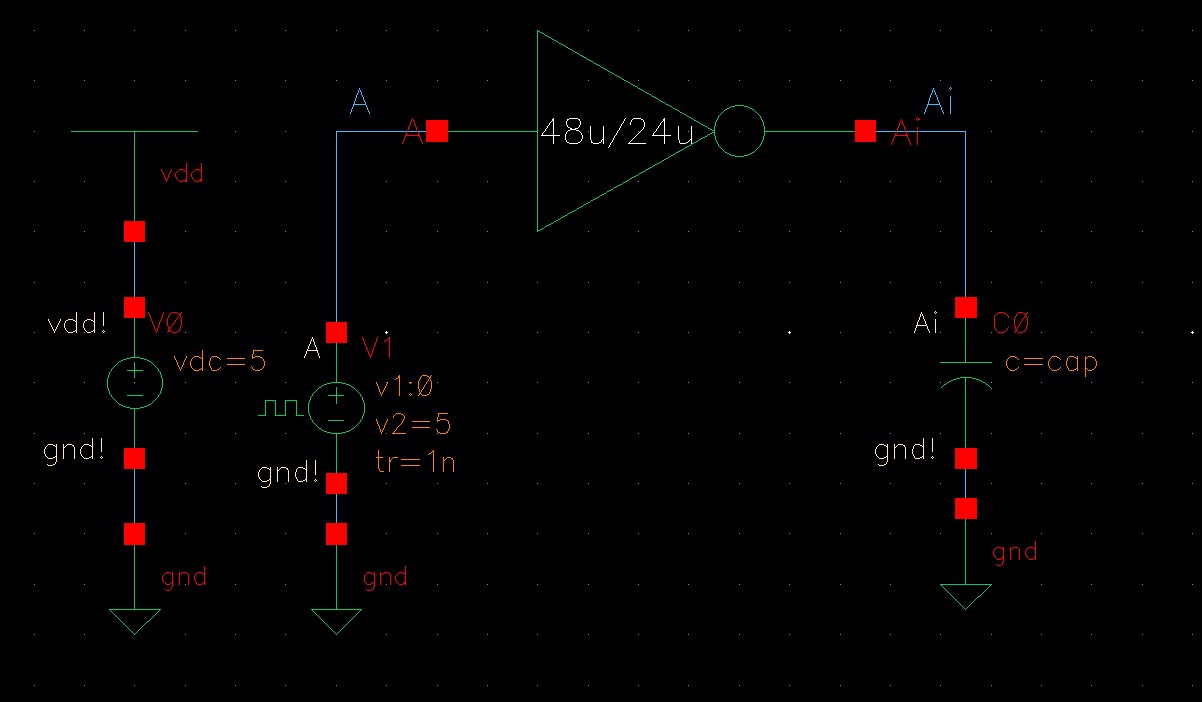
So for 48u/24u Inverter we have this:
The
next step is too the behavior of the inverters when changing the
capacitance loads. Think of capacitors as voltage stabilizers. The
bigger they are, the more they make the output signal steady and less
jumpy.
In addition, we will use Spectre and Ultrasim too see how
they change since Ultrasim is faster and when that happens, the result
might not be the same thing
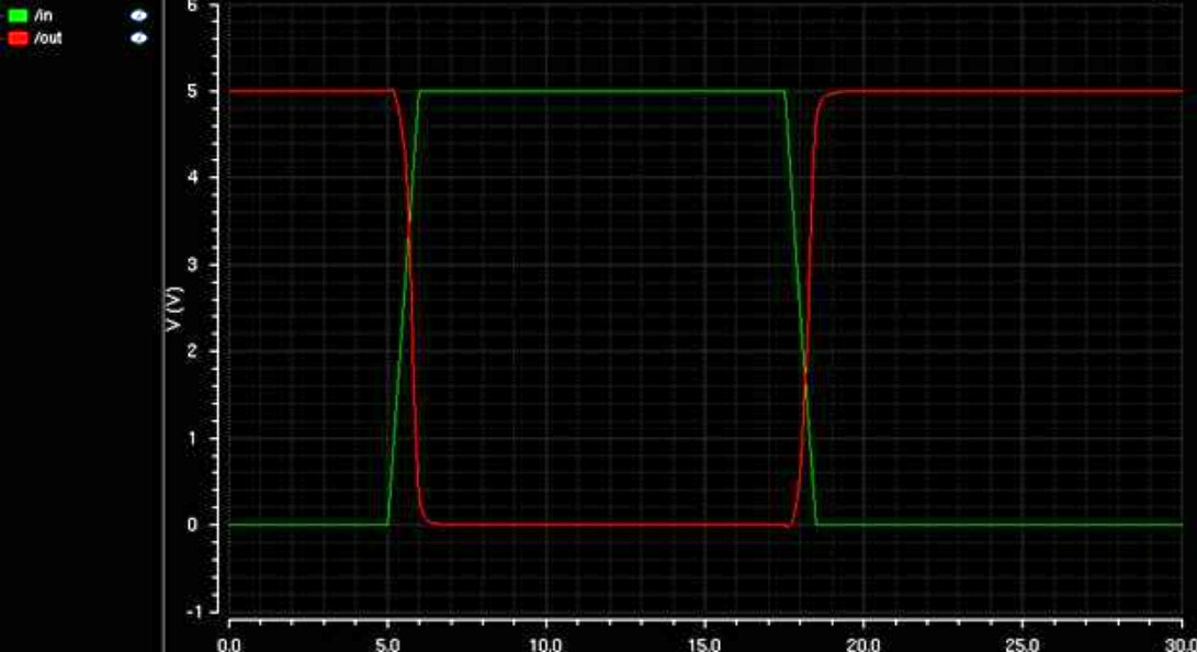
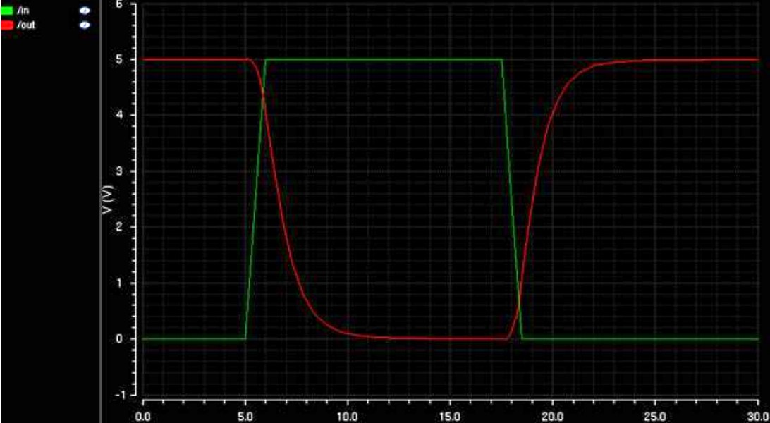
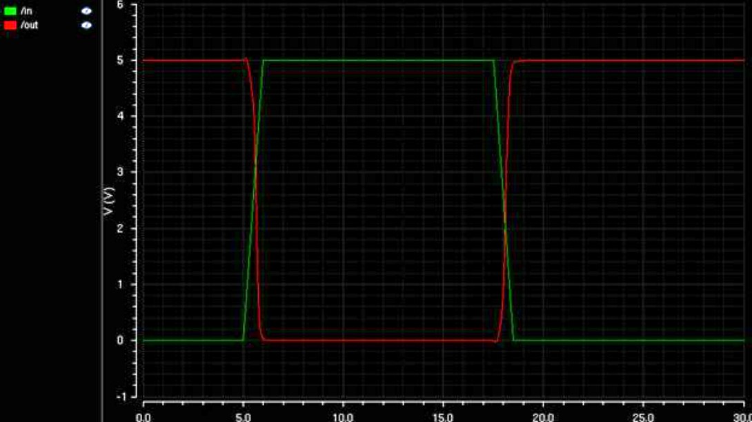
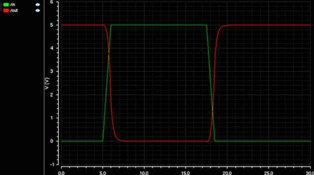
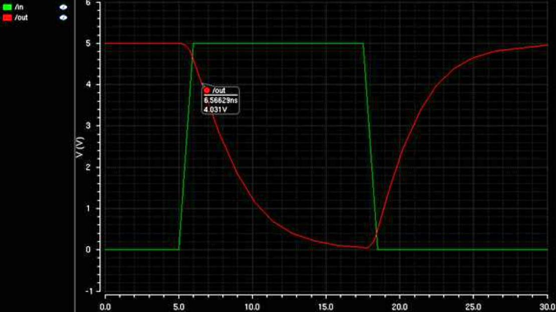
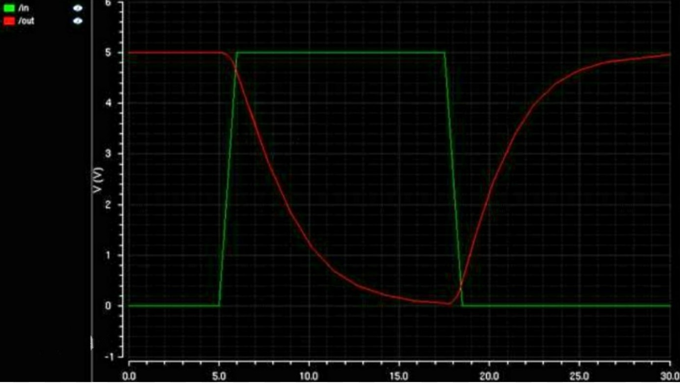
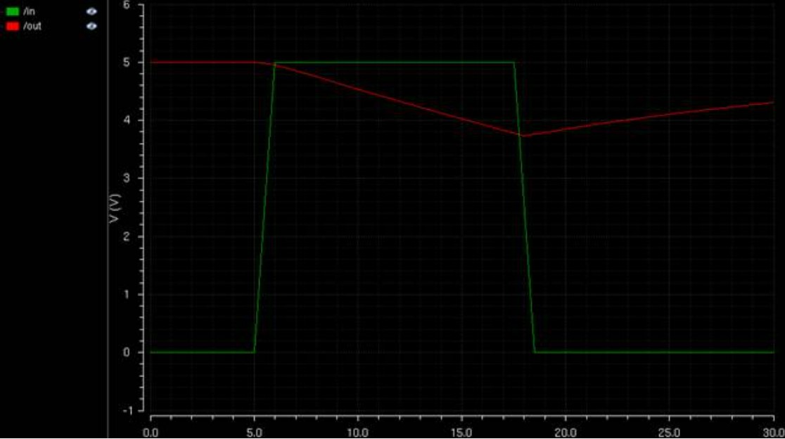
Here we will start with 12u/6u inverter. The capacitor will change as 100fF, 1pF, 10pF and 100pF as shown below.
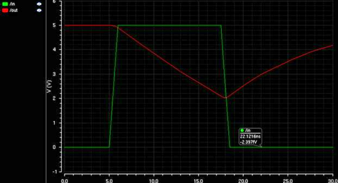
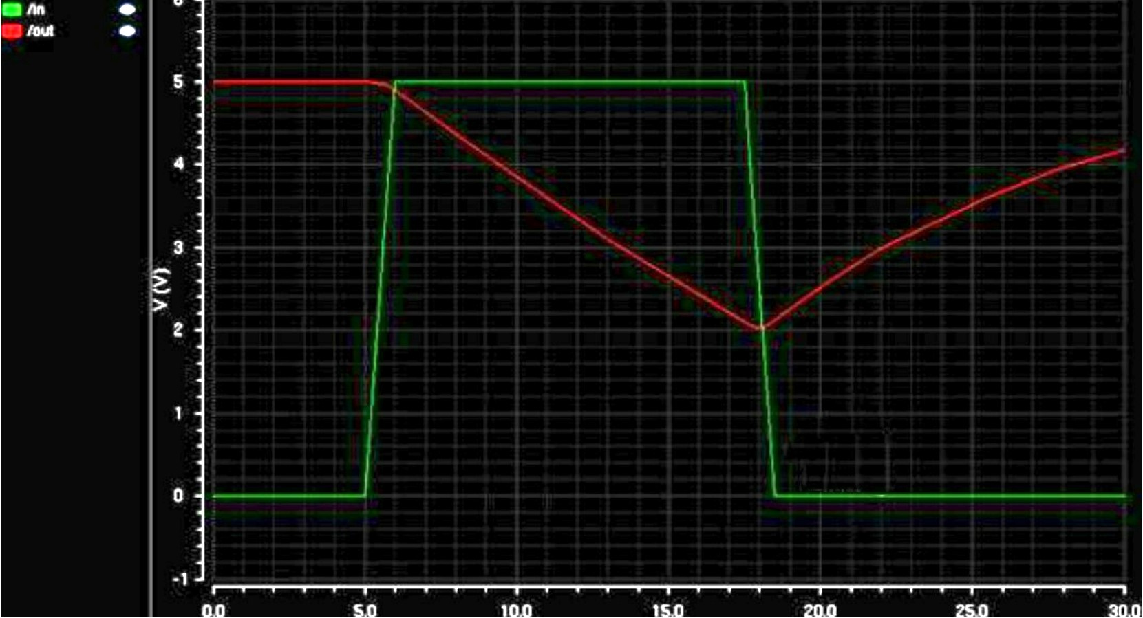
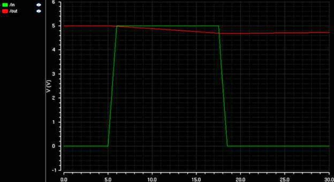
Looking
at these pictures, you can see that when the capacitor gets bigger, the
output wave gets smaller. This happens because the larger capacitor
takes more time to charge when the input signal passes through it. This
process makes the output wave smoother.
| Spectre | Ultrasim |
100fF
 |  |
1pF
 |  |
10pF
 |  |
100pF
 |  |
Same process but now with 48u/24u inverter
| Spectre | Ultrasim |
100fF
 |  |
1pF
 |  |
10pF
 |  |
100pF
 |  |
Based
on this, we can say that when the PMOS and NMOS transistors in an
inverter have a bigger size difference, it's better at handling higher
capacitance. In comparison, an inverter with PMOS and NMOS transistors
that are closer in size struggles more with high capacitance.
Back up
Return to EE 421L Labs