Lab 3 - ECE 421L
Authored
by Xavier Hernandez, hernax1@unlv.nevada.edu
8/18/23
Prelab Work
For the prelab, we were tasked to finish tutorial 1.
Tutorial
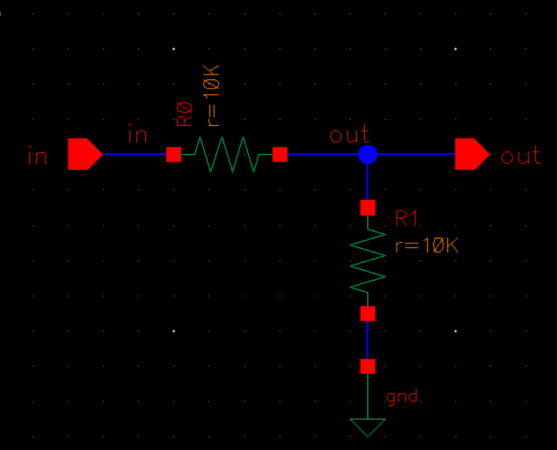
1 continued on with creating this schematic of a voltage divider using
10k ohm resistors. That substitued pins for some of the connections.
After,
we are tasked with creating a 10k ohm n well resistor. The values
specified by the tutorial are L = 56.1 and W = 4.5. We then add ntaps
on either side of the resistor, use the metal 1 layer and we add "L"
and "R" pins. Once we are done with that, we DRC check it, then extract
it.
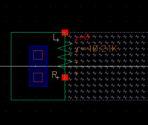
We
can then go into the extracted view of the nwell resistor and see the
value of the resistor we just created, as you can see, it provides a
resistance of 10.21k ohms
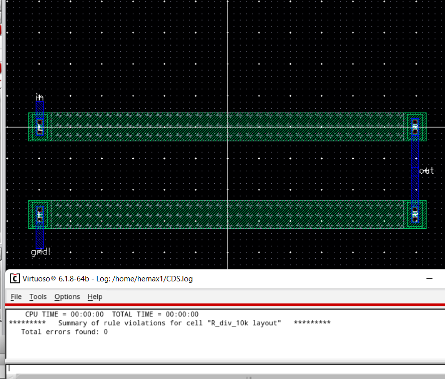
We
then create a layout of the voltage divider schematic, seen below. We
use our newly created 10k n-well resistors for the layout. Shown below
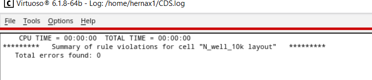
that it is DRC clean with 0 errors. After which we extract this layout.
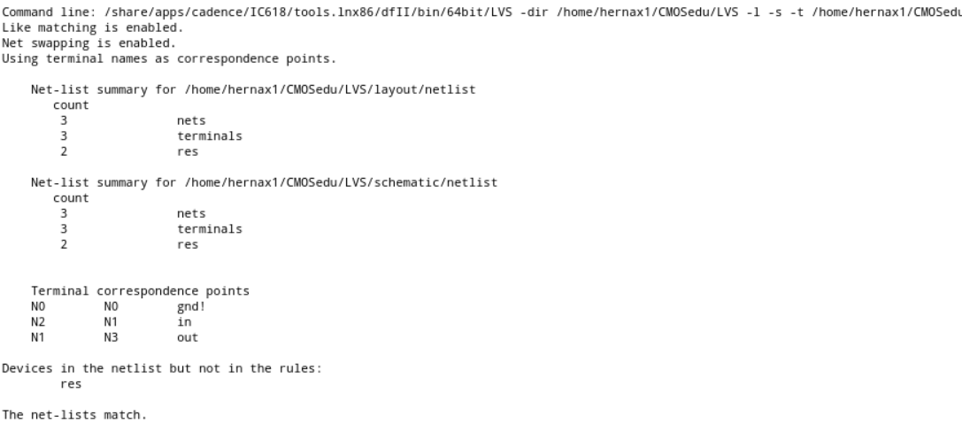
Finally,
the tutorial ends with us LVS checking the schematic and the layout of
the voltage divider. Seen below, we can see the netlists match. Aka, no
errors or discrepencies.
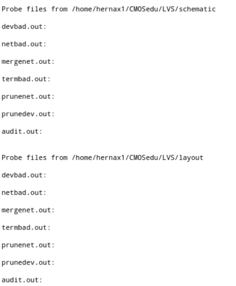
Netlists matching below.
Lab work
- Discussing selection of length and width
As we know from tutorial 1, using the dimensions from that tutorial gives us an extracted resistor of 10.21k ohms.
We
also know that the usual sheet resistance value is 855 ohm/square.
However that sheet resistance appears to differ from Cadence.
We
would prefer to get as close to 10k ohms. So we can reverse find the
exact R_square value that Cadence is calculating with based on the
extracted ohms value of 10.21k that we found.
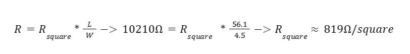
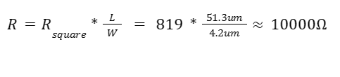
So
now we know that Cadence appears to have a sheet resistance that is
about 819 ohm/square. We can use this value to select our newlength and width
to more accurately represent our 10k ohm resistor.
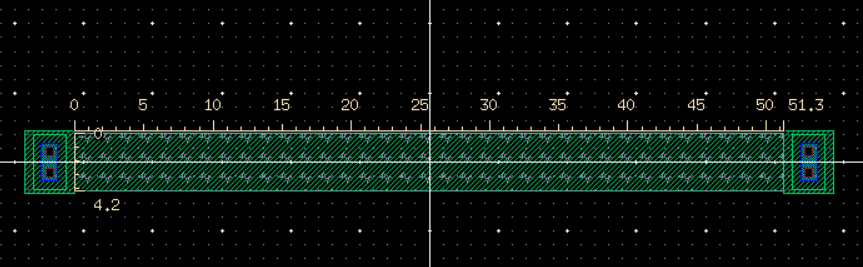
I selected the values L = 51.3um and W = 4.2um as they provided a value very close to 10k ohms. Seen below.
51.3um and 4.2um were additionally selected as they were divisble by .15um, thus no DRC errors.
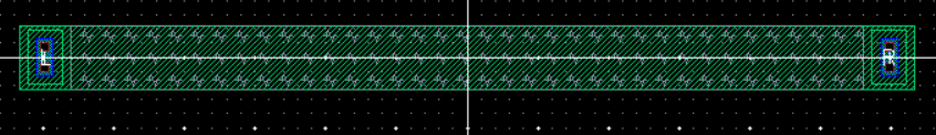
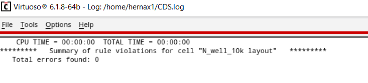
- DRC Clean n-well 10k resistor
Layout of resistor below, where the 10k n-well resistor is DRC clean.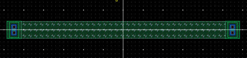
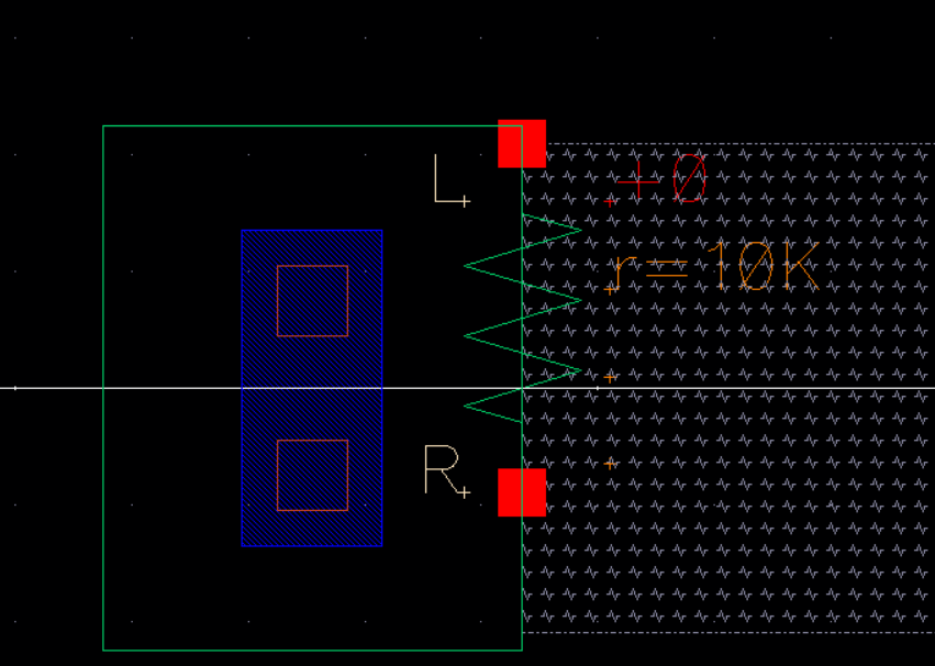
We can then extract our layout, seen below.
Now
that gives us an extracted view of the resistor that is very close to
10k ohms. Much better than the 10.21k ohms from the prelab.
- Measuring Length and Width
We
can measure length and width of our resistor using the "K" shortcut
keybind. This brings up the measurment window where we can simply
select ruler.
As seen below, our nwell resistor is 51.3 for length
and 4.2 for width. Which are the expected values used to determine our
resistance.
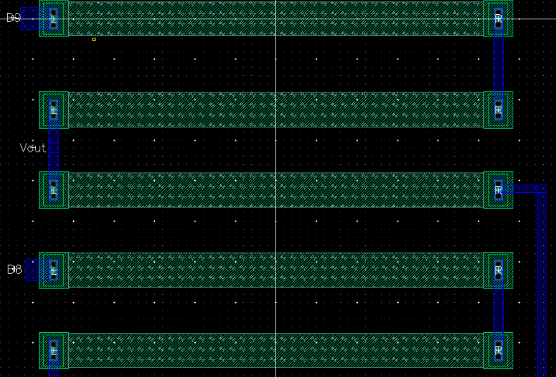
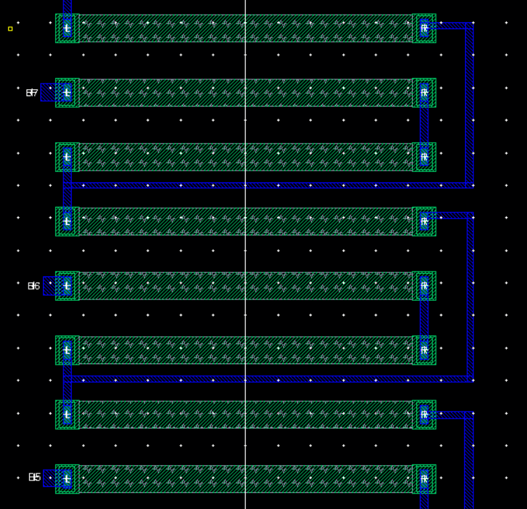
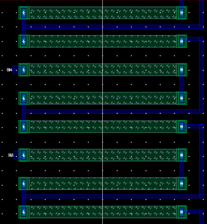
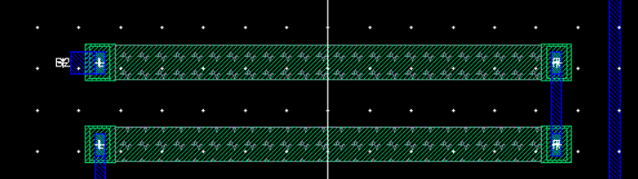
- DAC Layout with 10k Ohm Resistors
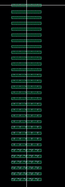
Counting
the resistors on the figure/schematic of lab 2, we notice that we need
31 10k ohm resistors in order to create our DAC layout.
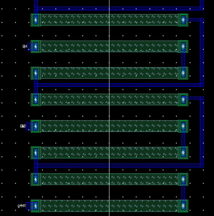
We lay out
31 resistors, seen below on the left, with varying y-positions.
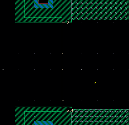
Additionally we can also measure the distance between each resistor,
remembering that we need a 5.4um minimum in order to comply with DRC
check, which is also satisfied on the right image below.
Next, we wire every resistor up.
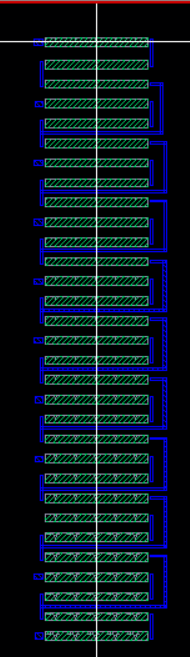
Below are close ups of the entire pins/wires of the DAC layout.
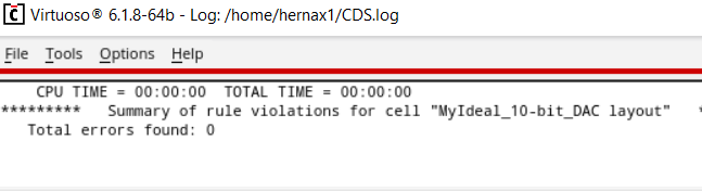
Finally we can DRC check our DAC layout, seen below passing with 0 errors.
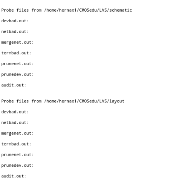
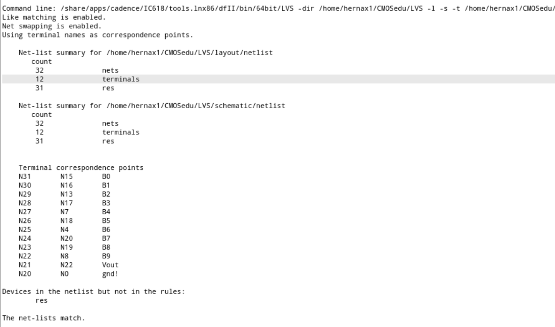
Now
that the layout passes DRC, we extract so that we can check LVS. Seen
below, LVS check passes and there no discrepencaires/errors
and netlists match.
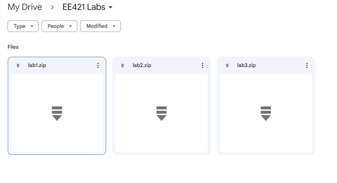
The files pertaining to this lab are located here.
Included are my adjusted 10k n_well resistor, and the schematic, layout and extracted view that were related to this lab only.
lab3work.zip
Shown below, lab stuff getting backed up.
Return to Xavier's Labs
Return to EE421 Labs