Lab 1 - ECE 421L
Authored
by Lucas Hagos,
hagosL1@unlv.nevada.edu
September 6th, 2023
Prelab:
For this prelab, we secured a CMOSedu account and looked through the "Editing Webpages" tutorial seen here.
---------------------------------------------------------------------------------------------------------------------------------------------------------------------------
Lab Description:
In this lab, we went through the first part of Tutorial 1 seen here.
Afterwards, we created the lab1.htm report in a folder (also called lab1) in our CMOSedu accounts (seen below).
---------------------------------------------------------------------------------------------------------------------------------------------------------------------------
Lab Report:
In this lab, I completed half of the very first cadence tutorial, of which there are six.
I began by setting up Cadence, which was done by by deleting and replacing 3 files, divaDRC.rul, divaEXT.rul and divaLVS.rul.
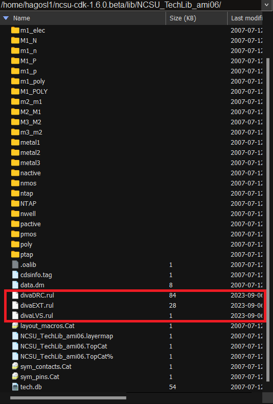
These files were replaced with updated versions of themselves, as the old ones were pointing to the wrong location.
With this setup complete, I ran Virtuoso and opened the Library Manager, where we were able to create a new library.
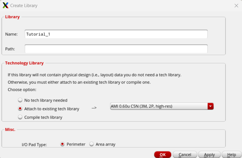
It is worth noting that we attached the preexisting "AMI 0.6u" library to our new "Tutorial_1" library.
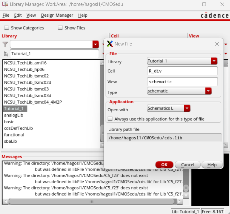
Inside our newly made library, we created a new file inside of it, named "R_div"
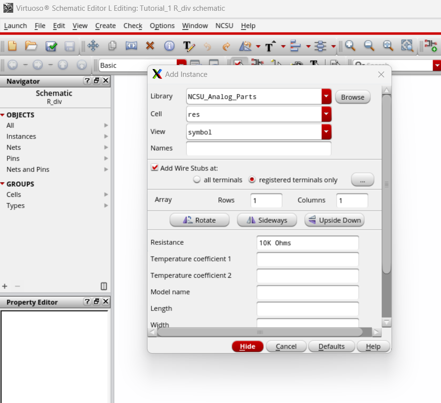
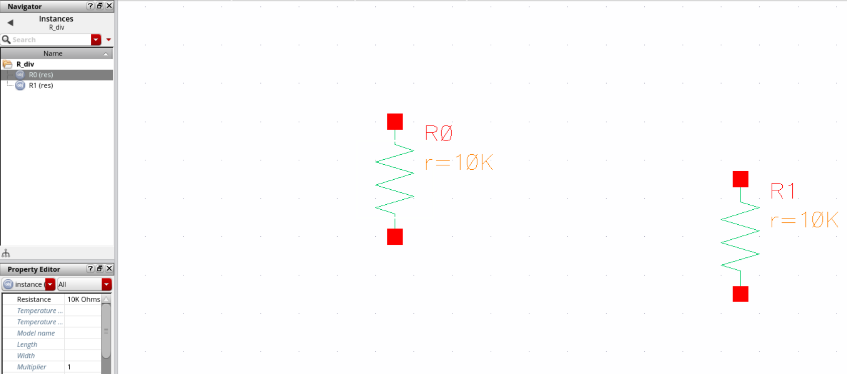
Moving
to the Schematic Editor window, I used the Bindkey "i" to bring up the
Add Instance window. I then accessed the NSCU_Analog_Parts library to
make a 10K Ohm Resistor.
Hiding
the Add Instance window, I added two of the 10k resistors, used the "f"
binkey to bring the resistors into view and pressed Escape in order
leave the "Create Instance" mode.
It's
worth noting that many functions or commands, like move or rotate, are
not "single use" and will remain active until you press the Escape key.
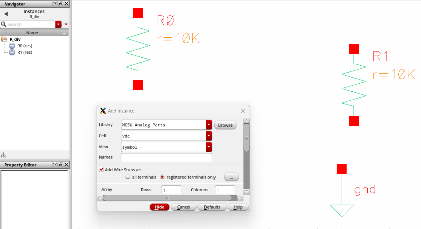
I then repeated the exact same process used to create the resistors,
only this time opting to creat a ground node and a DC voltage source
(whose cell names were gnd and vdc).
It
was important to use the "q" bindkey to access the object properties of
the DC Voltage source and give it a voltage of 1. Otherwise, it would
never receive a value.
Now that all the Circuit components were
present. I was able to use wire them all together using the "w" bindkey
to create a wire and lead it to and from each component.
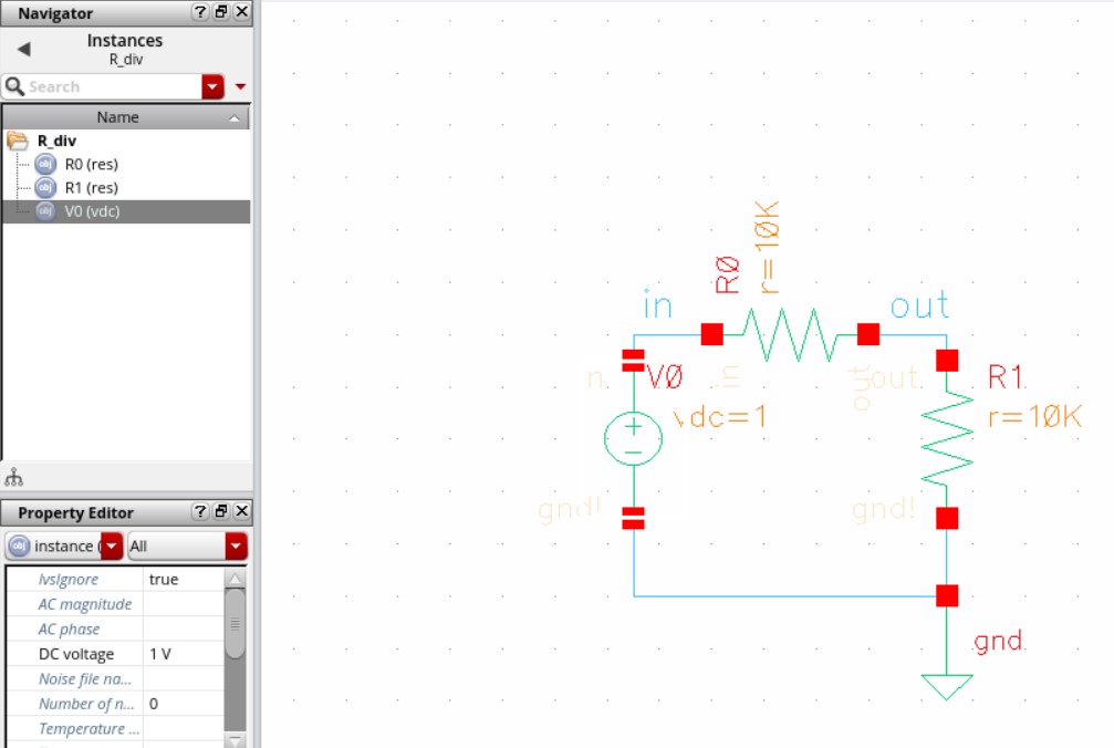
Before that, I used the "r" and "m" bindkeys to rotate and move each component in order to organize the circuit.
I
then labeled two of the wires using the "l" (lowercase L) bindkey. In
addition to making the circuit visually appealing, this can help in
graphing circuit inputs and outputs.
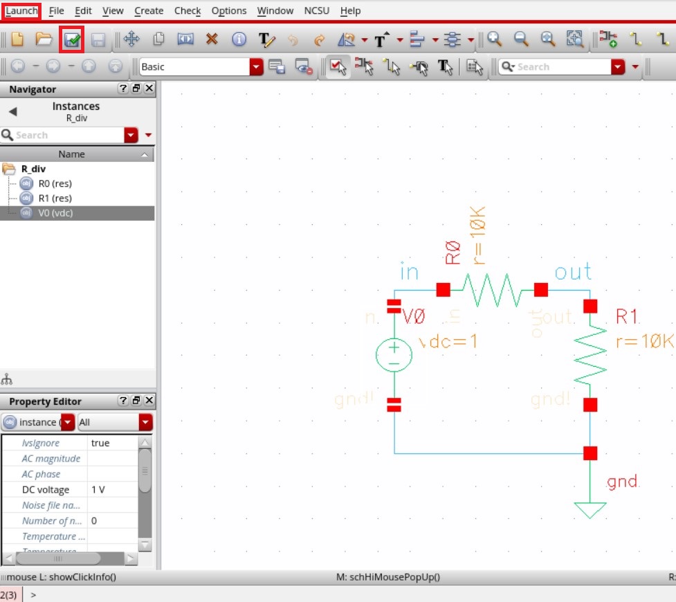
Once
the circuit was ready to be simulated, I saved and checked the file by
clicking the floppy disk with the green checkmark over it. (seen above).
After that, I brought up the ADE L window by clicking Launch (also seen above) and clicking "ADE L" on the drop-down menu.
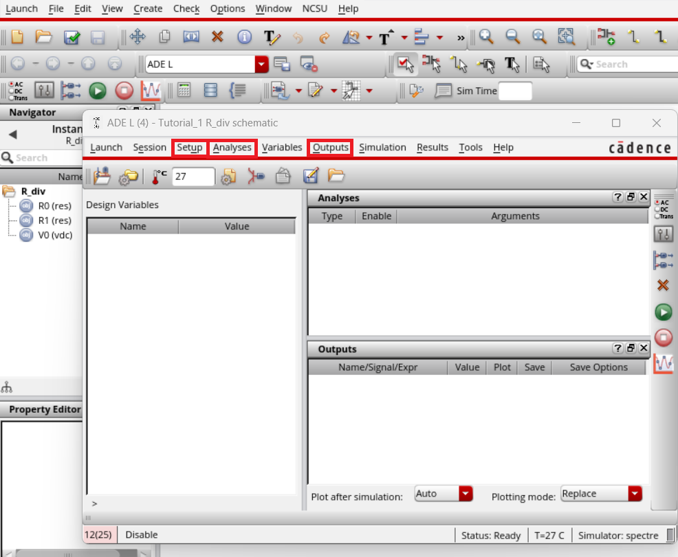
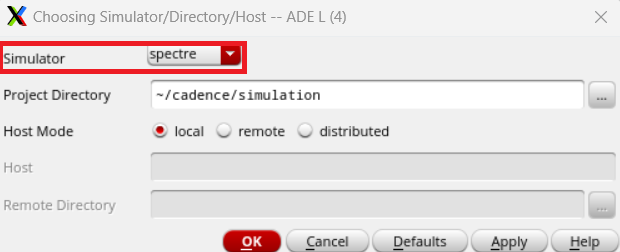
With
access to the ADE L window, I first verified the simulator was set to
spectre by going to Setup (seen above) and clicking on
Simulator/Directory/Host on the drop-down menu.
Once the corresponding window opened, I was able to confirm spectre was the chosen simulator.
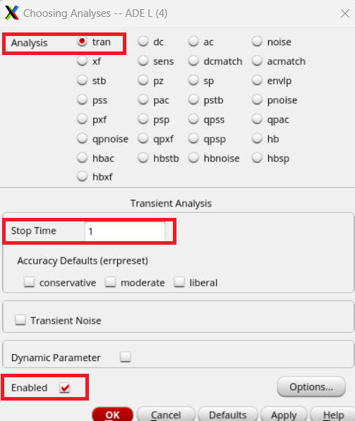
I
then made sure the analysis in question would be a transient analysis.
This was done by clicking Analysis (seen two photos above) and clicking
"choose" on the drop-down menu.
Once the corresponding window
opened, I confirmed the transient analysis, added a stop time of 1
second, and activated the "Enabled" box.
Selecting
the signals we needed to plot required me to click on "Output" (seen
three photos above) and then clicking "To Be Plotted" > "Select on
Design" in the drop-down menus.
I then went back to the circuit
window and clicked on the "in" and "out" wire labels. This added both
labels to the list of outputs.
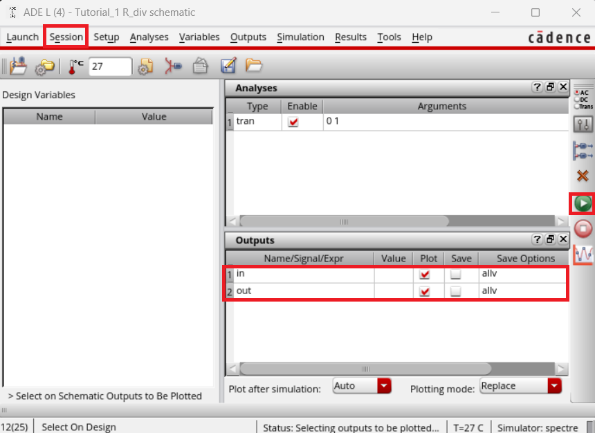
Right
before I ran the simulation, I first saved this information, so that
when I needed to simulate this circuit later I wouldn't need to repeat
what I had done. This was done by clicking on "Session" (seen above).
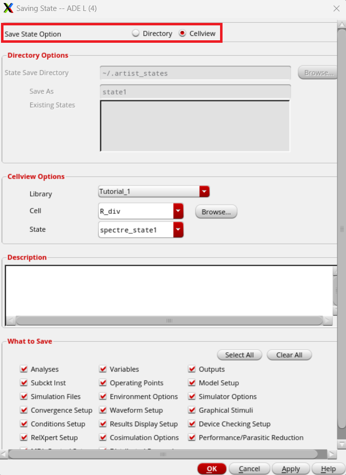
This brought up the "Saving State" window.
In the Saving State
window, I made sure that the Save State Option had Cellview confirmed
before hitting OK and closing the window.
All that remained was to run the simulation, which was done by hitting the green "go" button (seen two photos above).
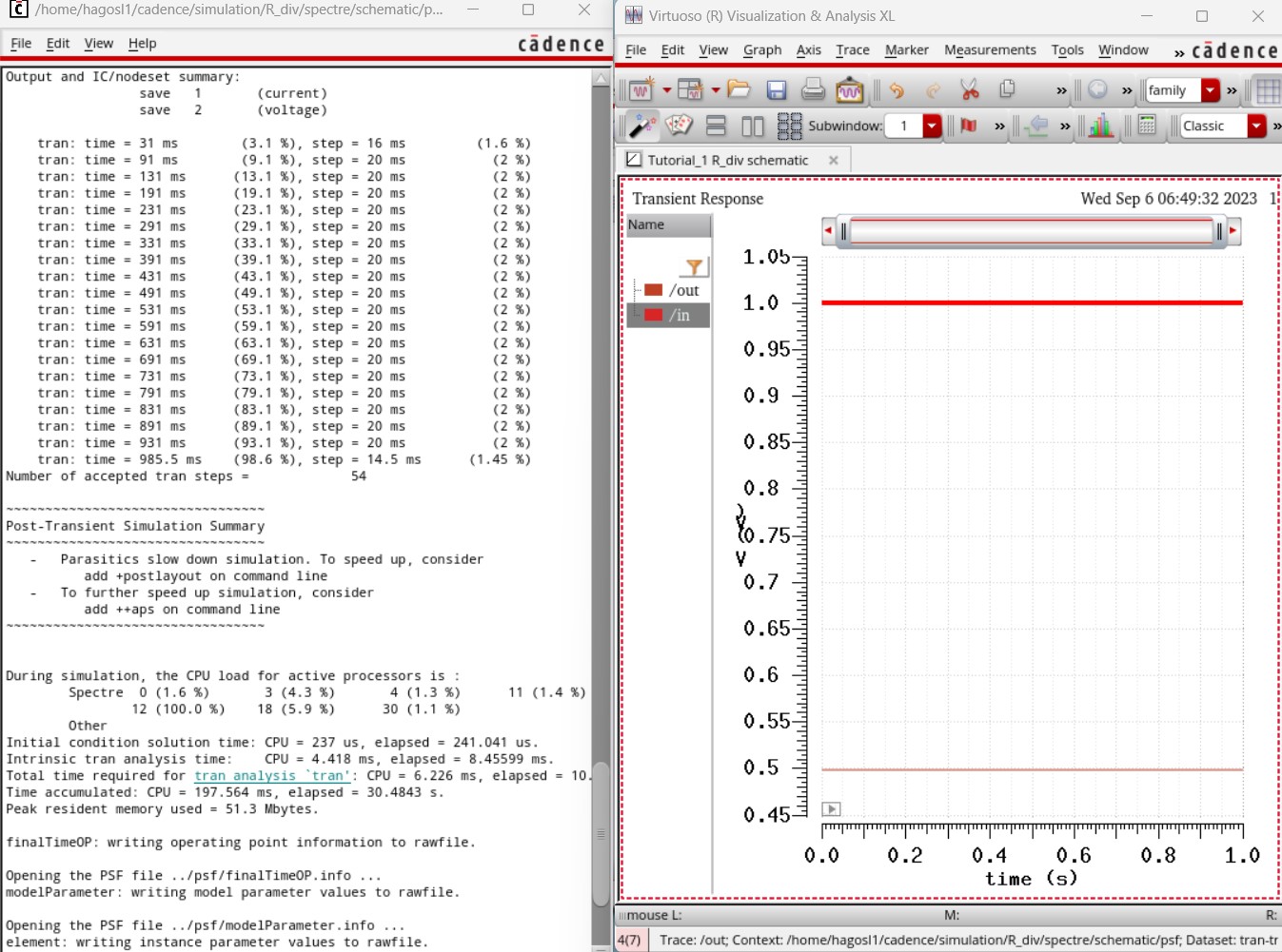
With that, the first portion of the first tutorial was complete.
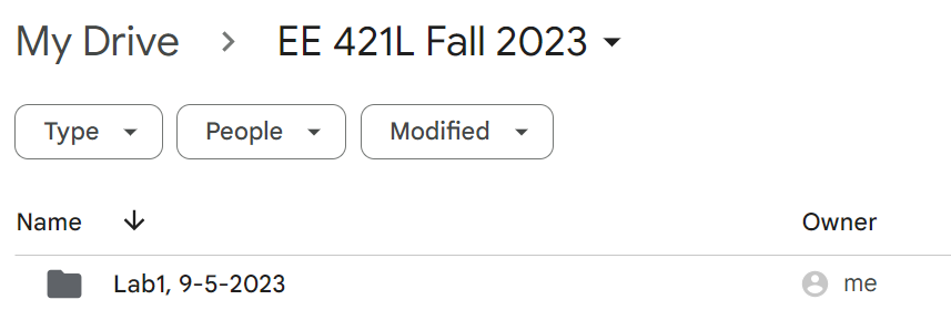
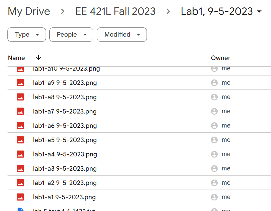
However,
as is the case with any important work, constant and thorough backups
are extremely encouraged. These backups may take the form of self-sent
emails, uploads to the one's google drive, or a combination of the two.
Regardless of how the backups are made, it is imporant to include the
date a file is made in the name of the file (seen below).
fin
Return to my labs
Return to EE 421 Labs