Lab 5 - ECE 421L
Authored
by Kyle Abenojar, abenok1@unlv.nevada.edu
October 11th, 2023
Prelab:
For lab 5, we were tasked with completing Tutorial 3 for our prelab.
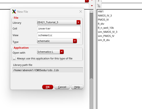
The first step is create a new schematic titled "inverter".
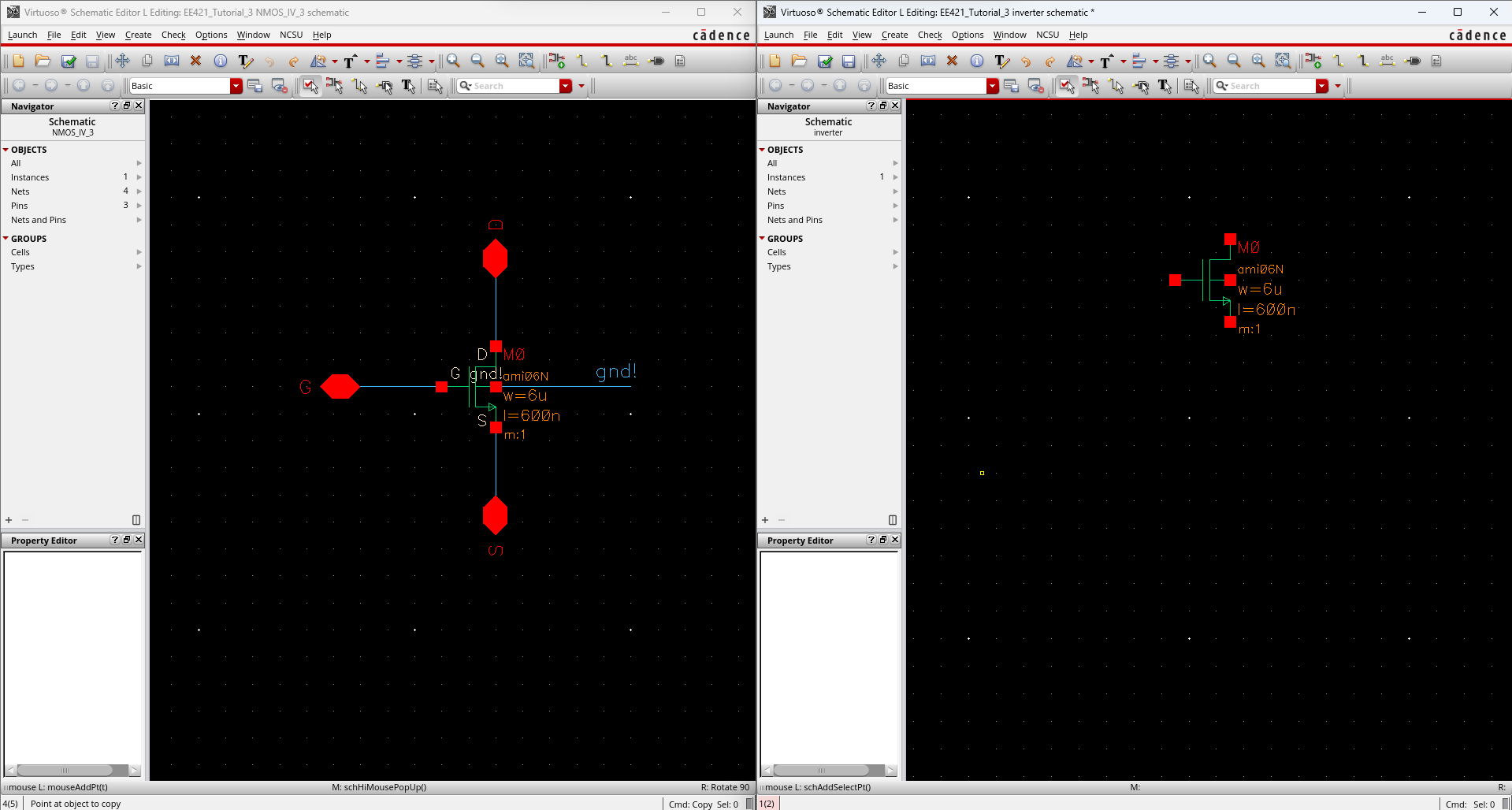
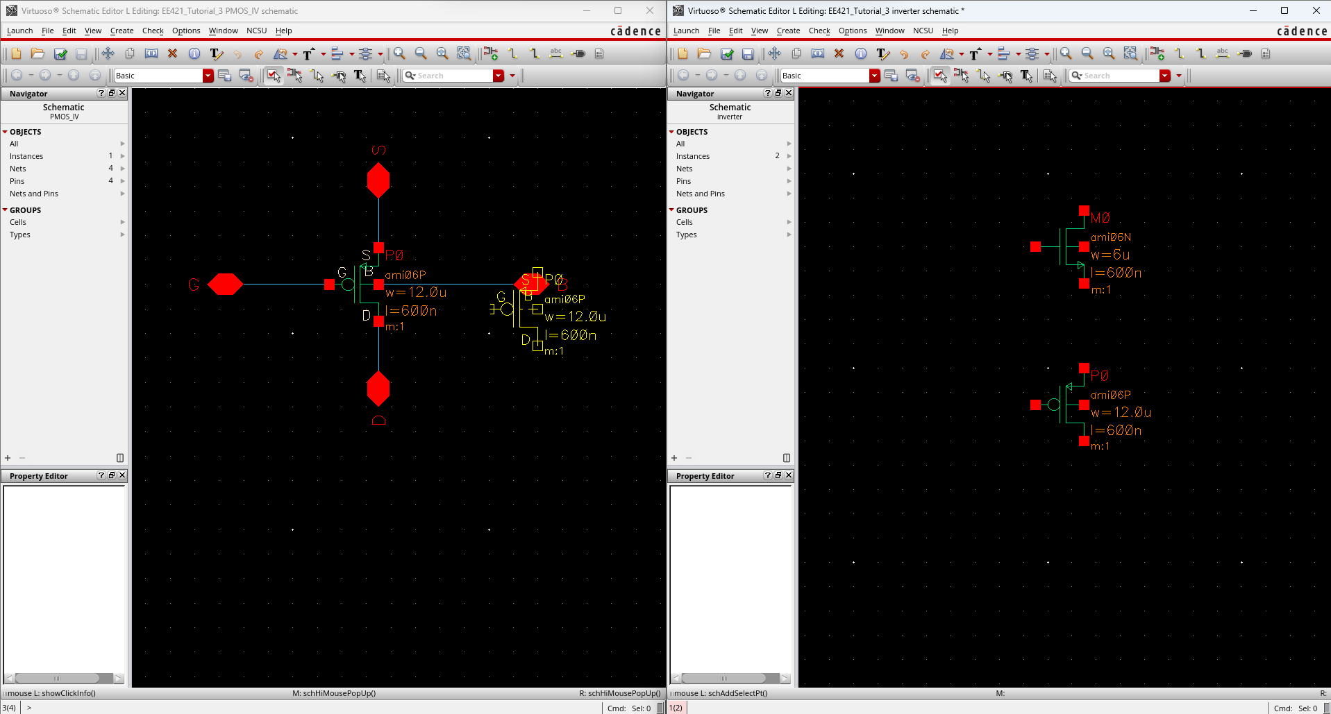
We
can then open up our previous NMOS and PMOS schematics and copy and
paste our NMOS and PMOS cells onto our new inverter schematic.
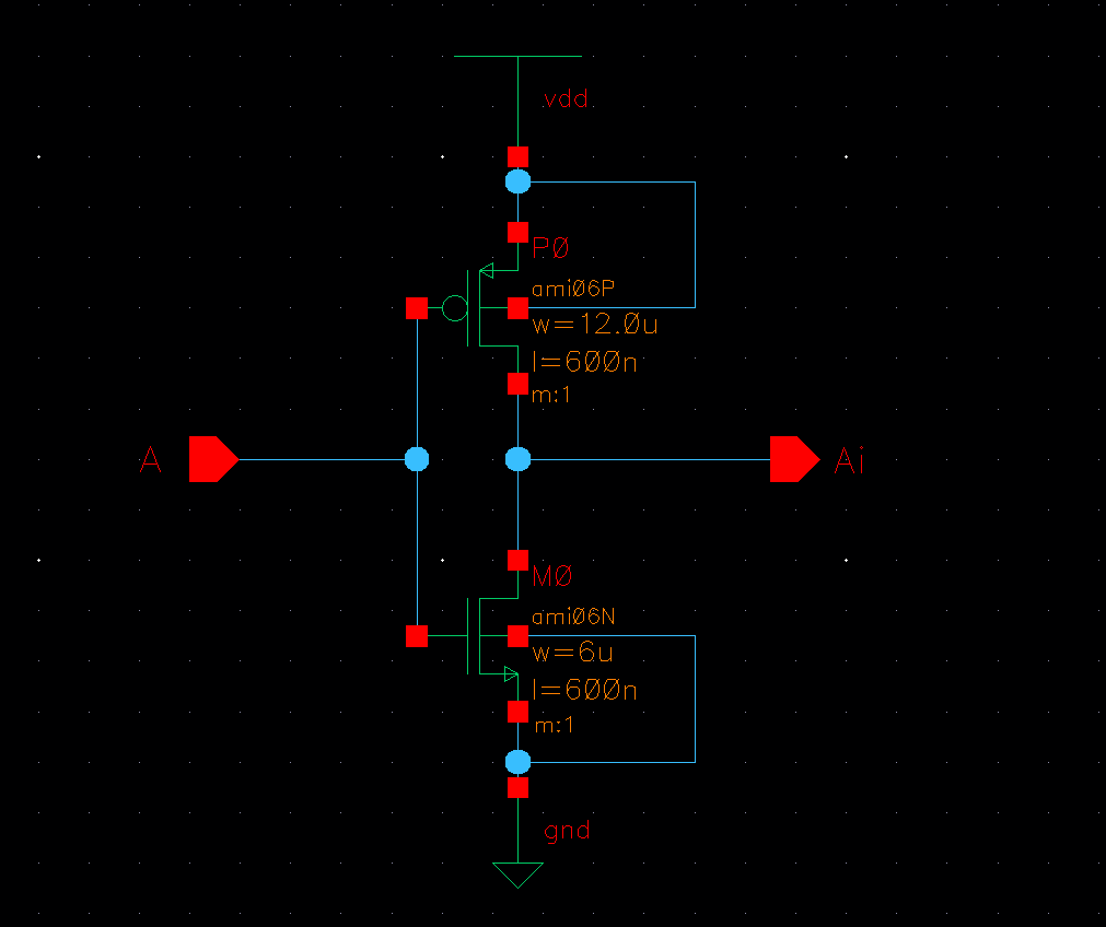
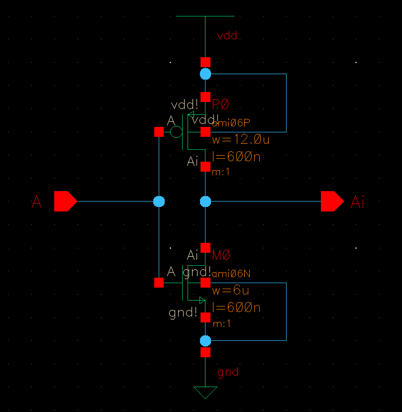
Next,
I added vdd and ground to my schematic as well as pins for A (input)
and Ai (output) then wired them all together to get the following.
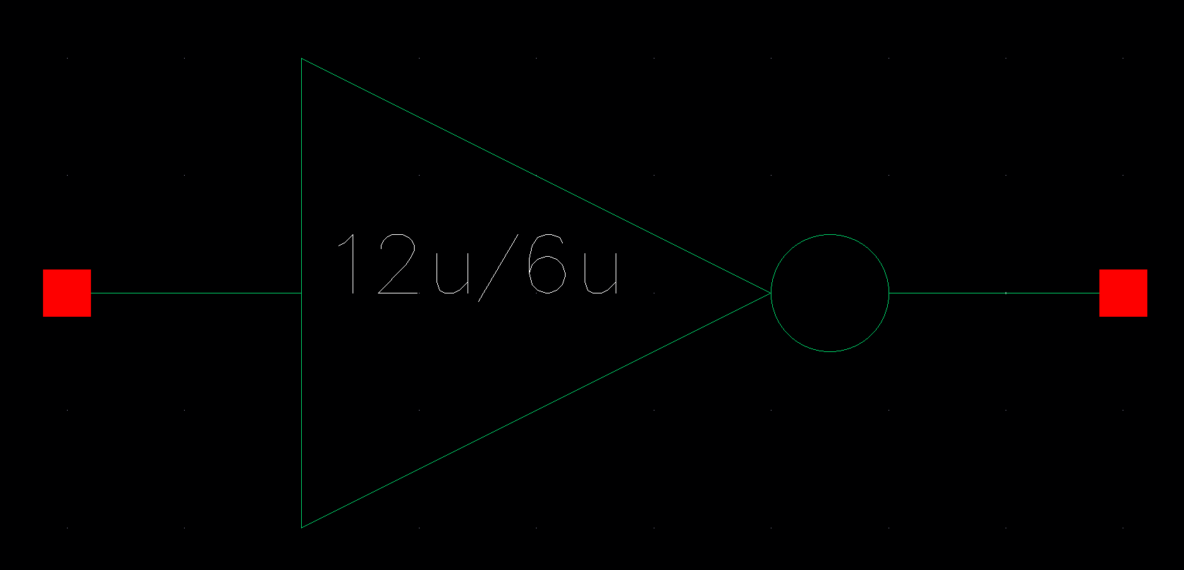
After DRCing my schematic and ensuring there are no errors, I then created a symbol for my inverter
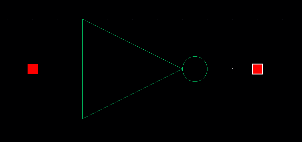
After
ensuring there were no errors with my symbol, I then created a new
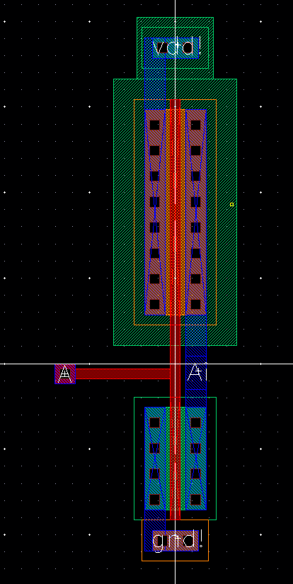
layout view for my inverter and placed a PMOS, NMOS, ptap, ntap and
m1_poly to get the following
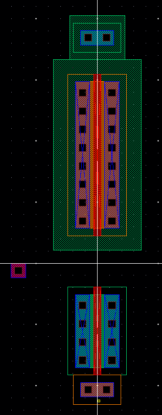
I
then added metal to connect the drains of the PMOS and NMOS. I also
added metal to connect the source of the NMOS to ground and to connect
the source of the PMOS to vdd. I also added poly to connect the gates
of the NMOS and the PMOS. Lastly, I added pins for my input A, output
Ai, vdd! and gnd!.
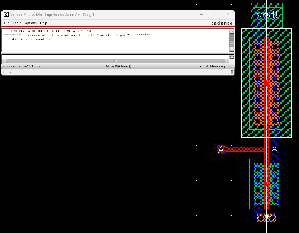
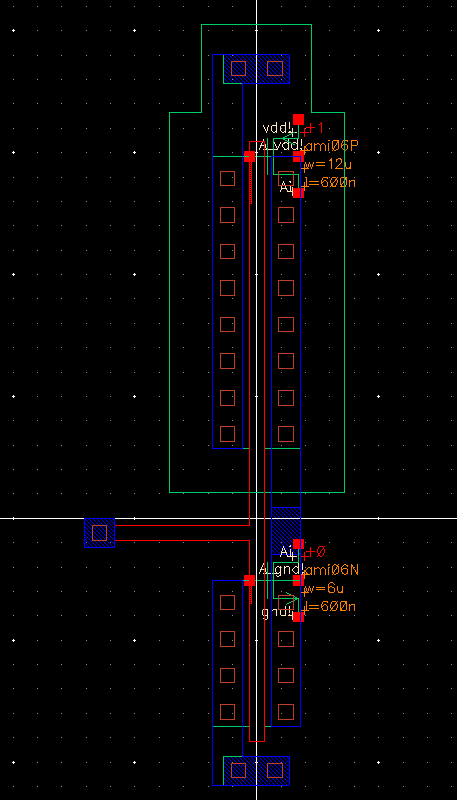
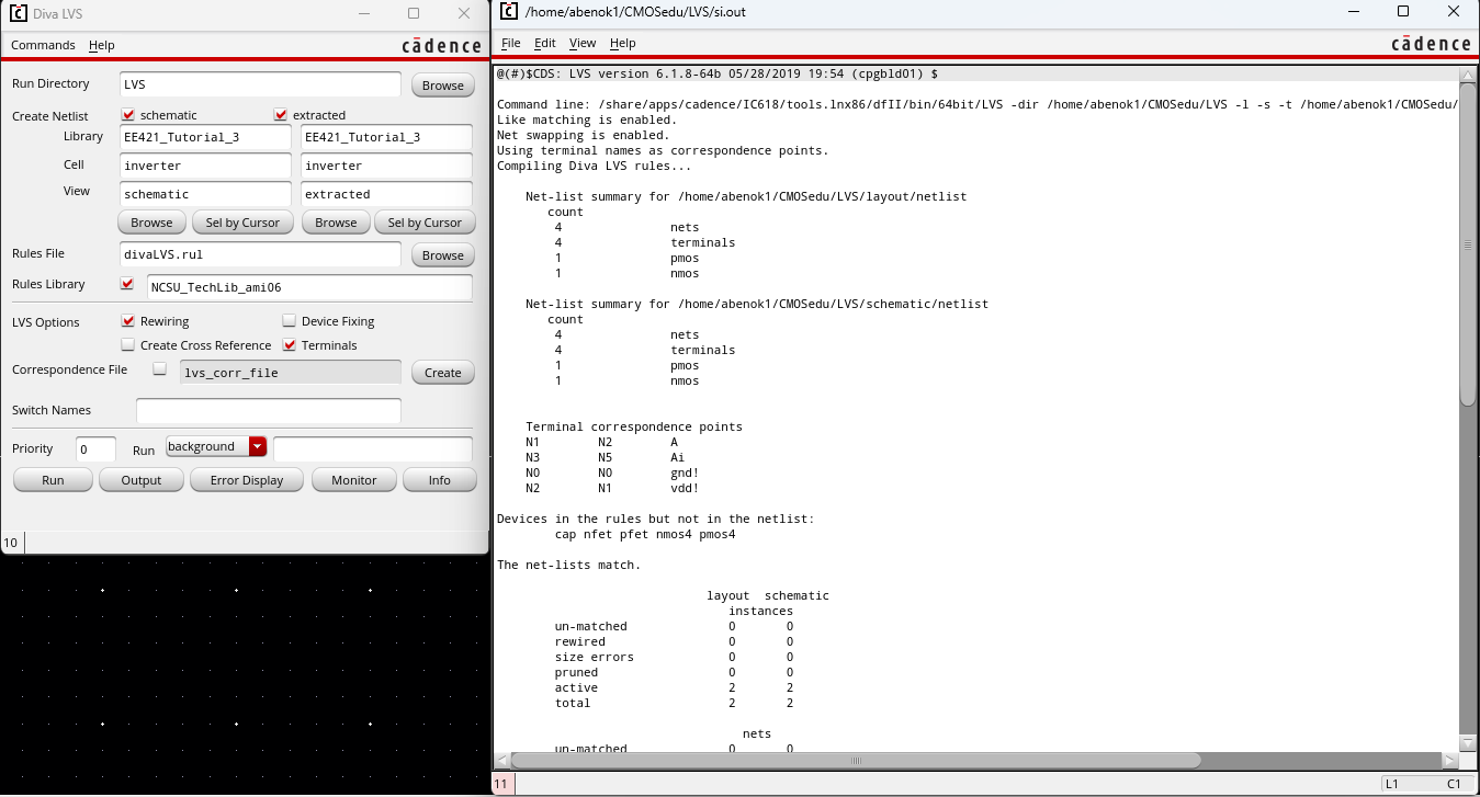
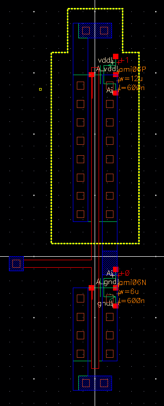
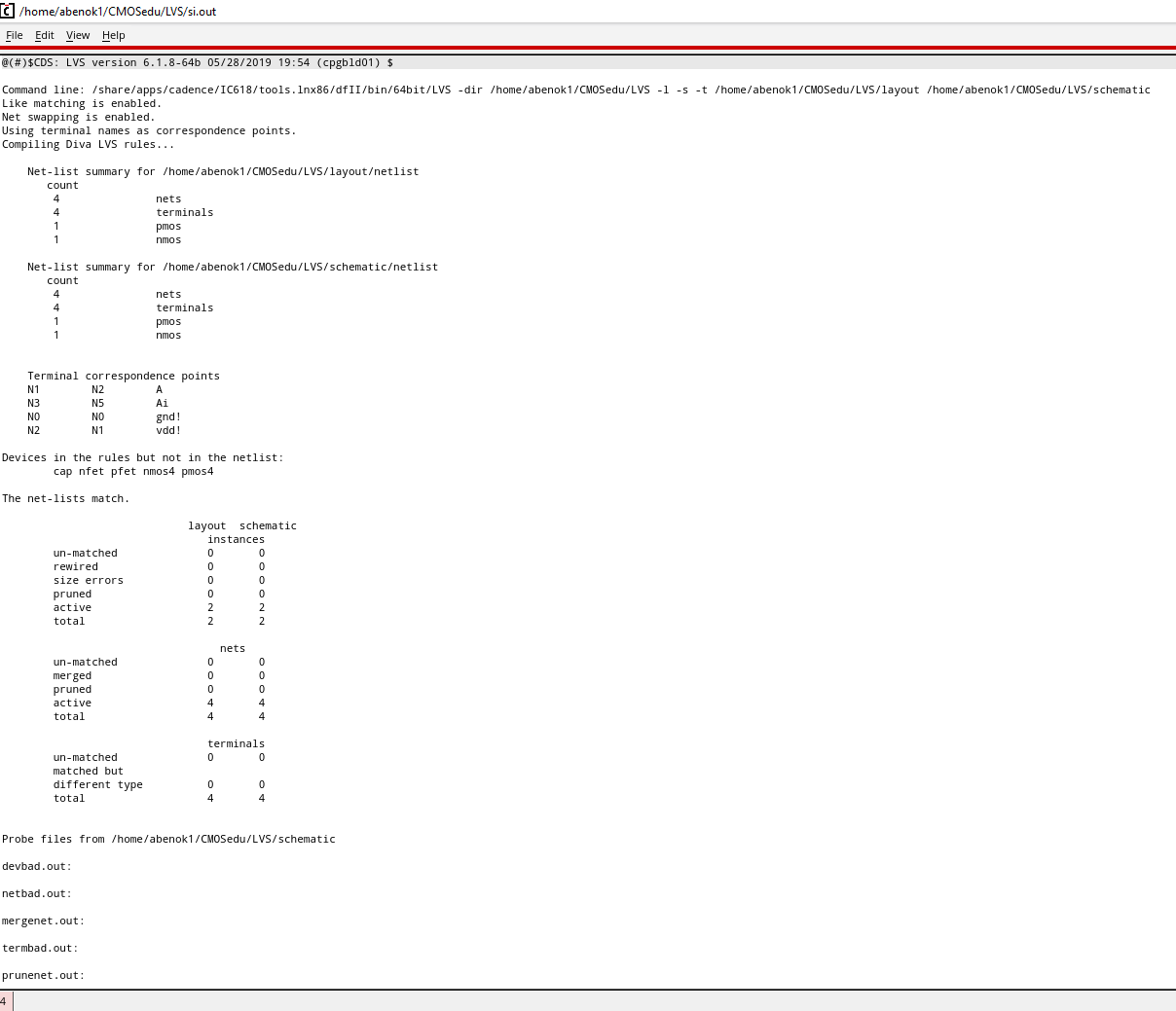
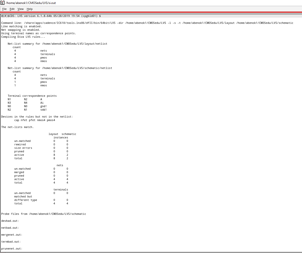
After this, I extracted my layout to get the following. I also performed an LVS to ensure that my netlists matched.
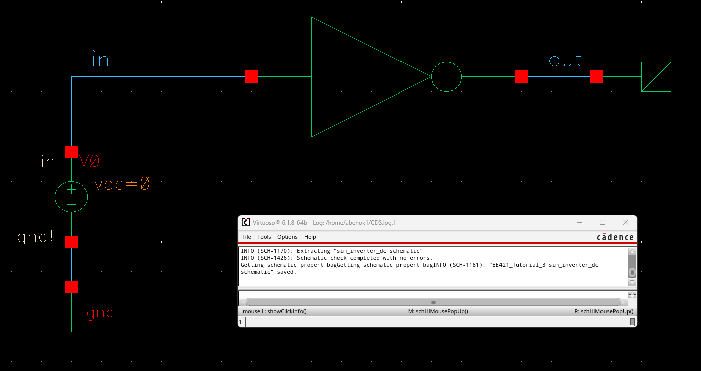
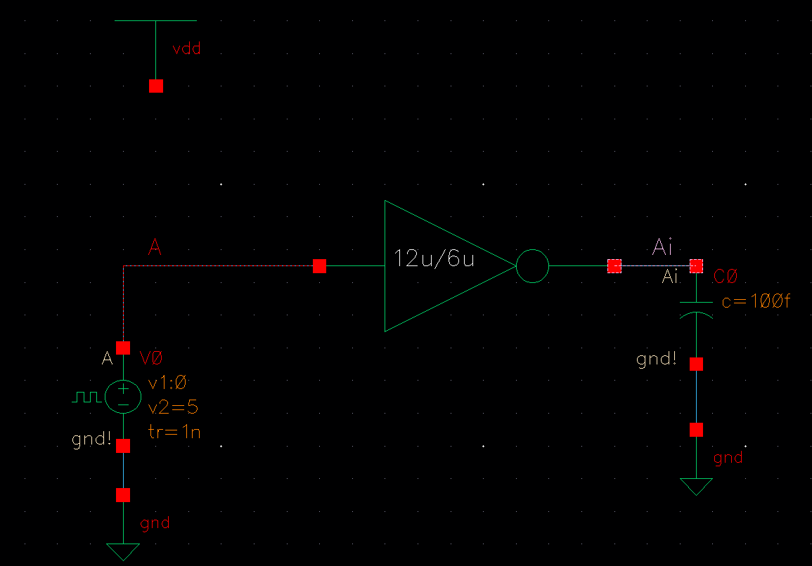
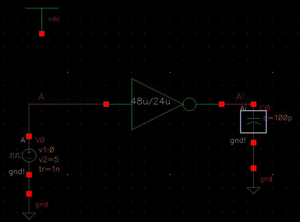
Next, I created a new schematic to simulate my inverter.
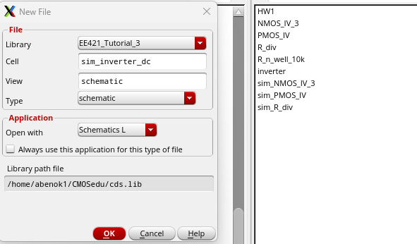
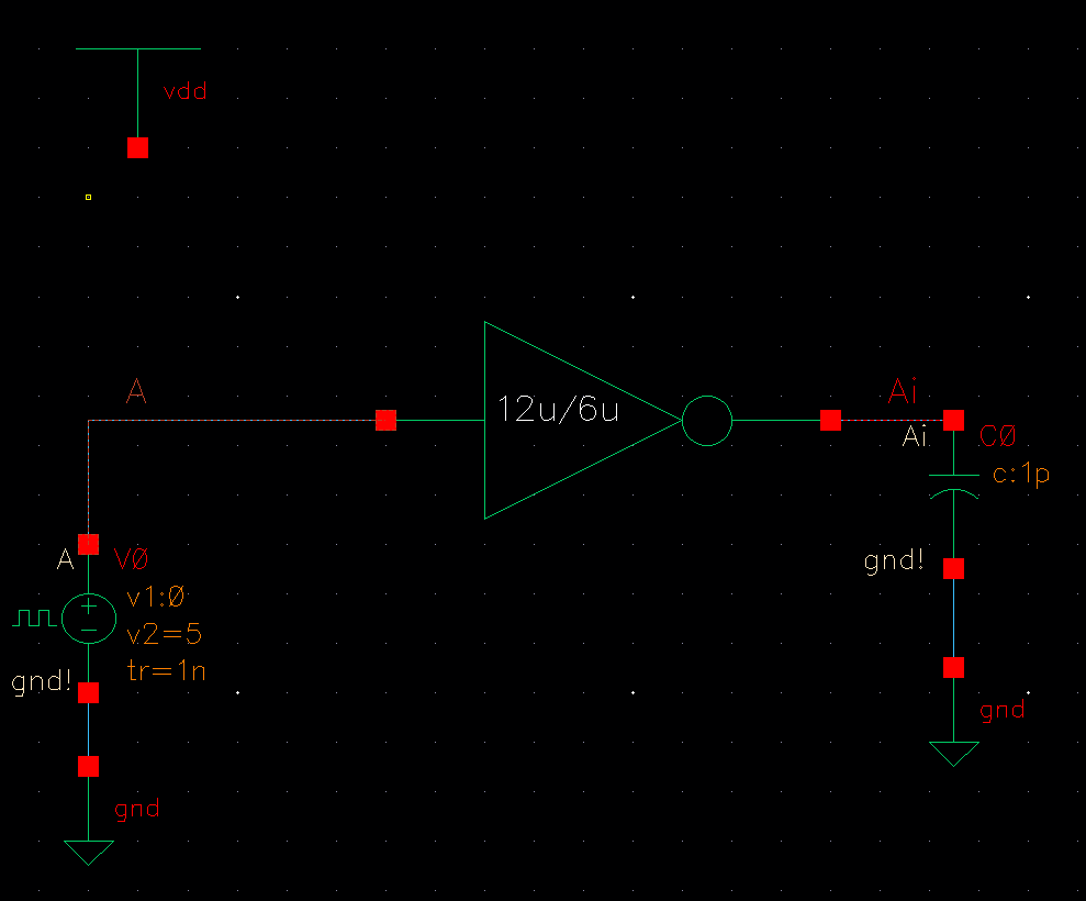
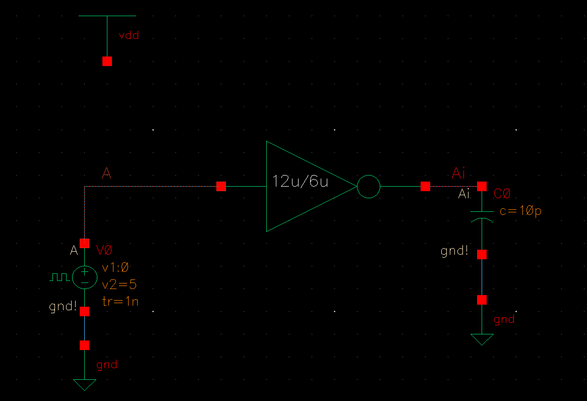
Using my inverter symbol, I generated the following schematic.
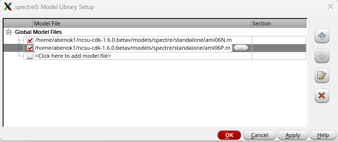
After launching the ADE L, I changed the model library to include the proper files.
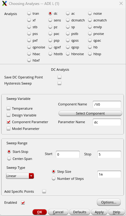
I then setup a dc analysis using the following parameters.
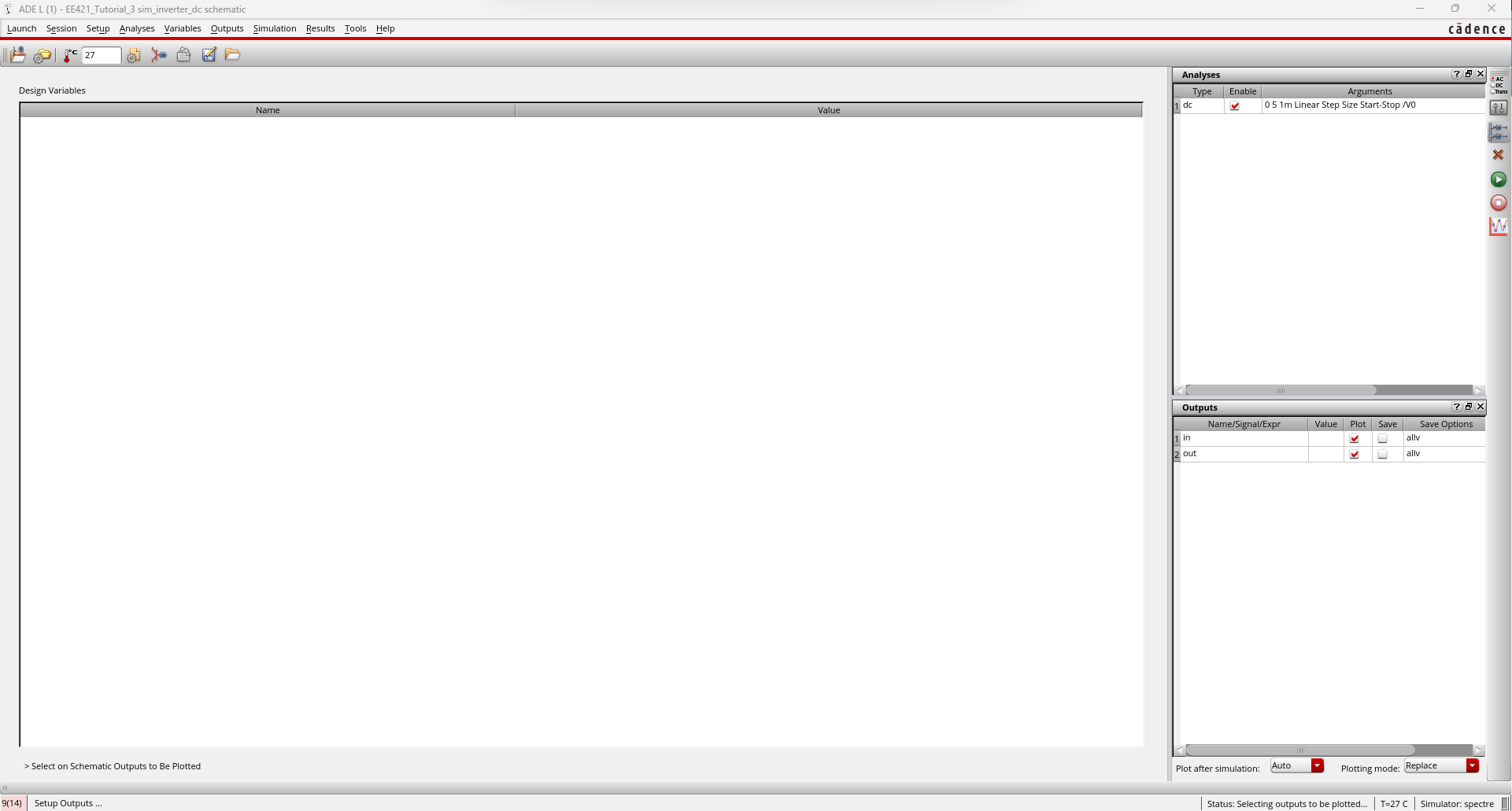
After choosing my outputs to chart, my window looked like the following.
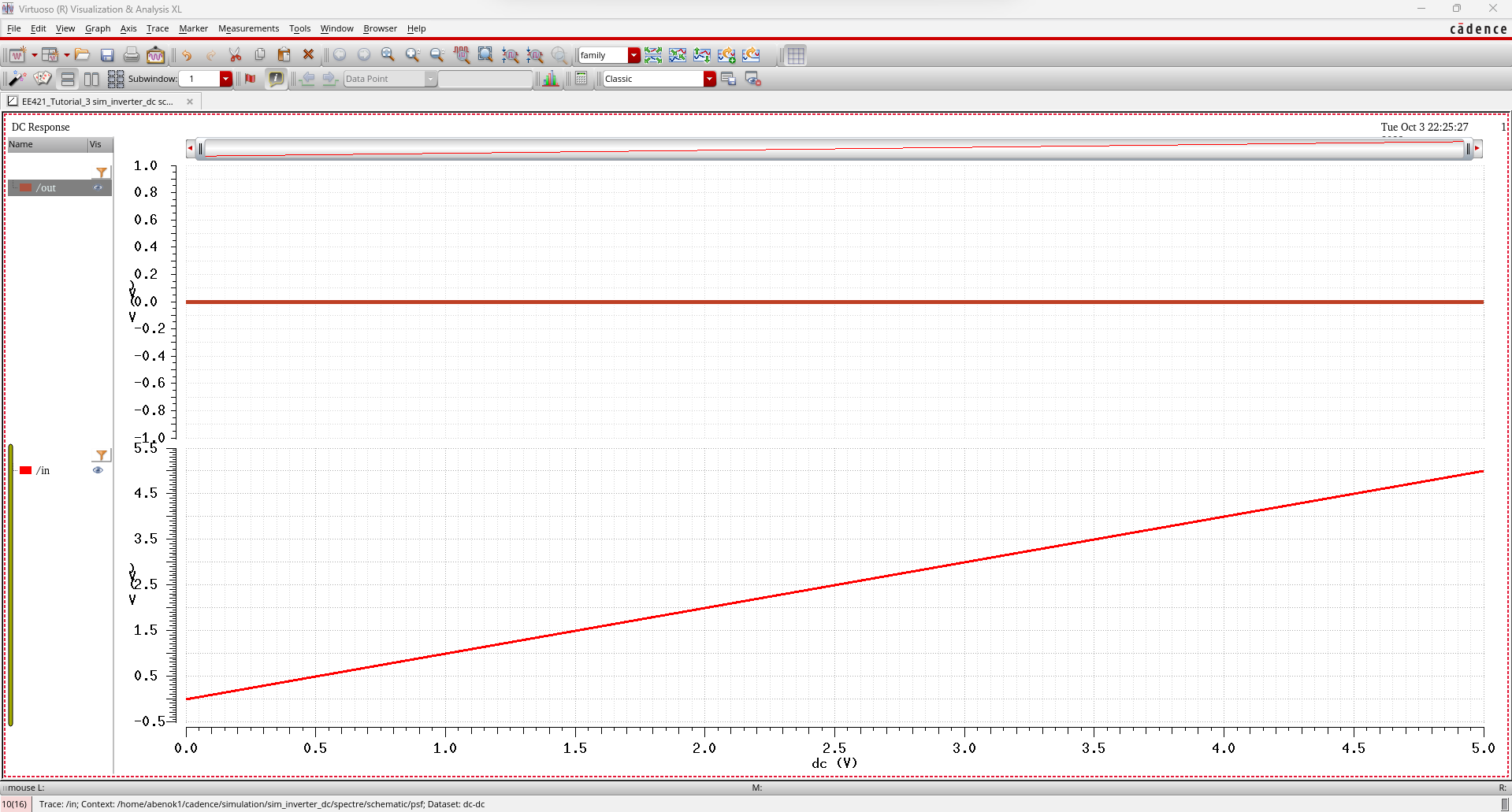
I
then ran my simulation however, as we can see, our results aren't what
we expected. That's becuase we didn't include vdd in our simulation.
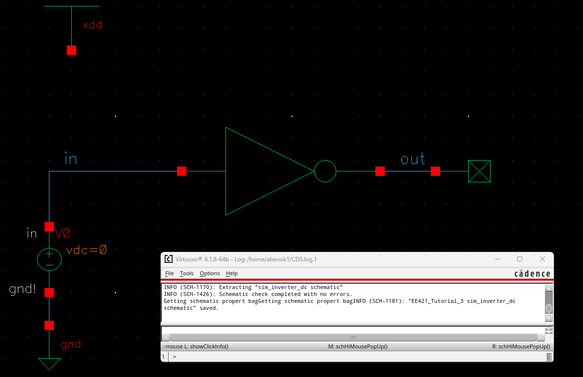
First, we go back to our schematic and add vdd.
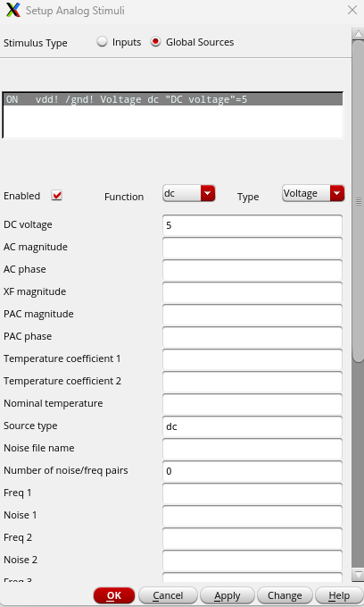
Then, back in the ADE L, we set up vdd as an analog stimuli at 5V.
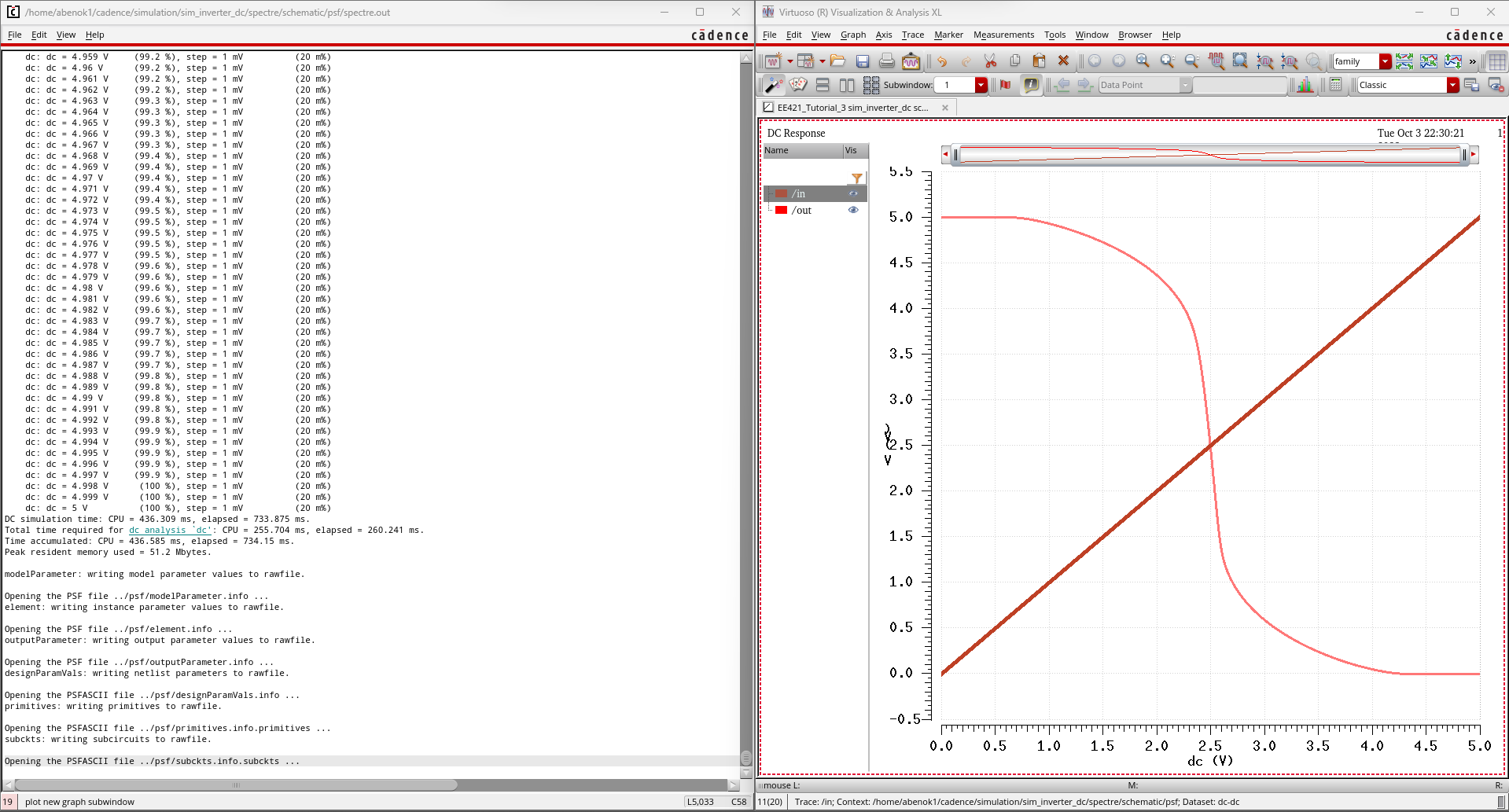
Now, when we simulate our device, we get the proper input and output.
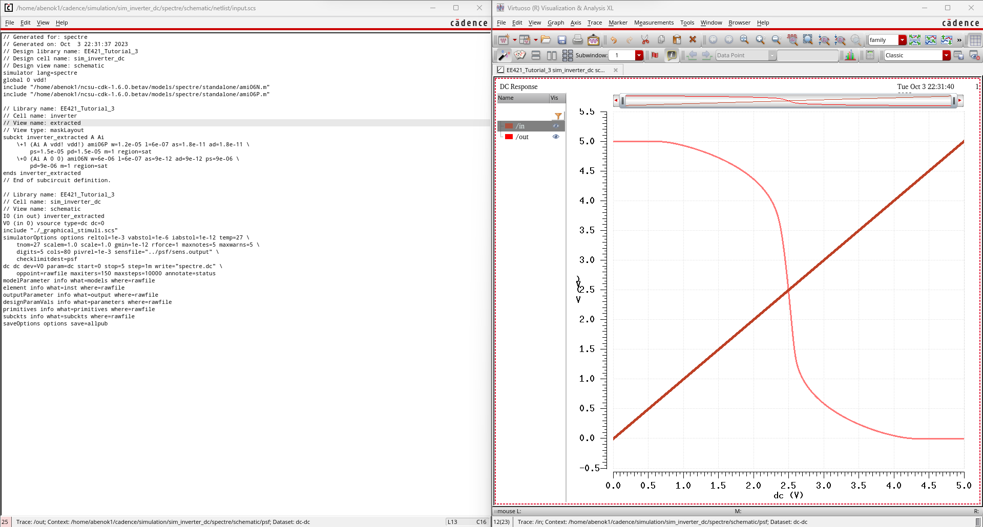
Next, we simulate our extracted schematic and as expected, we get the same graph.
Lab Report:
For
the first part of this lab, I used the 12u/6u inverter that we created
during the prelab while performing Tutorial 3. Below are the schematic,
symbol, layout, extracted view, and LVS Results.
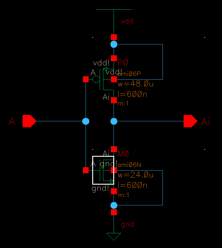
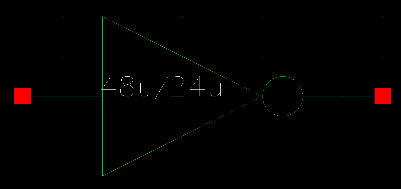
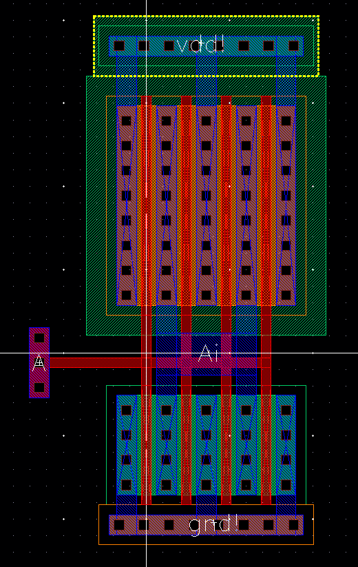
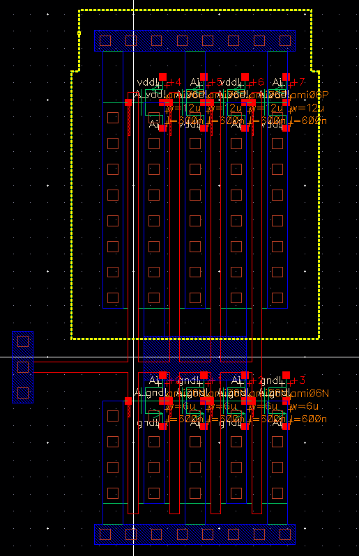
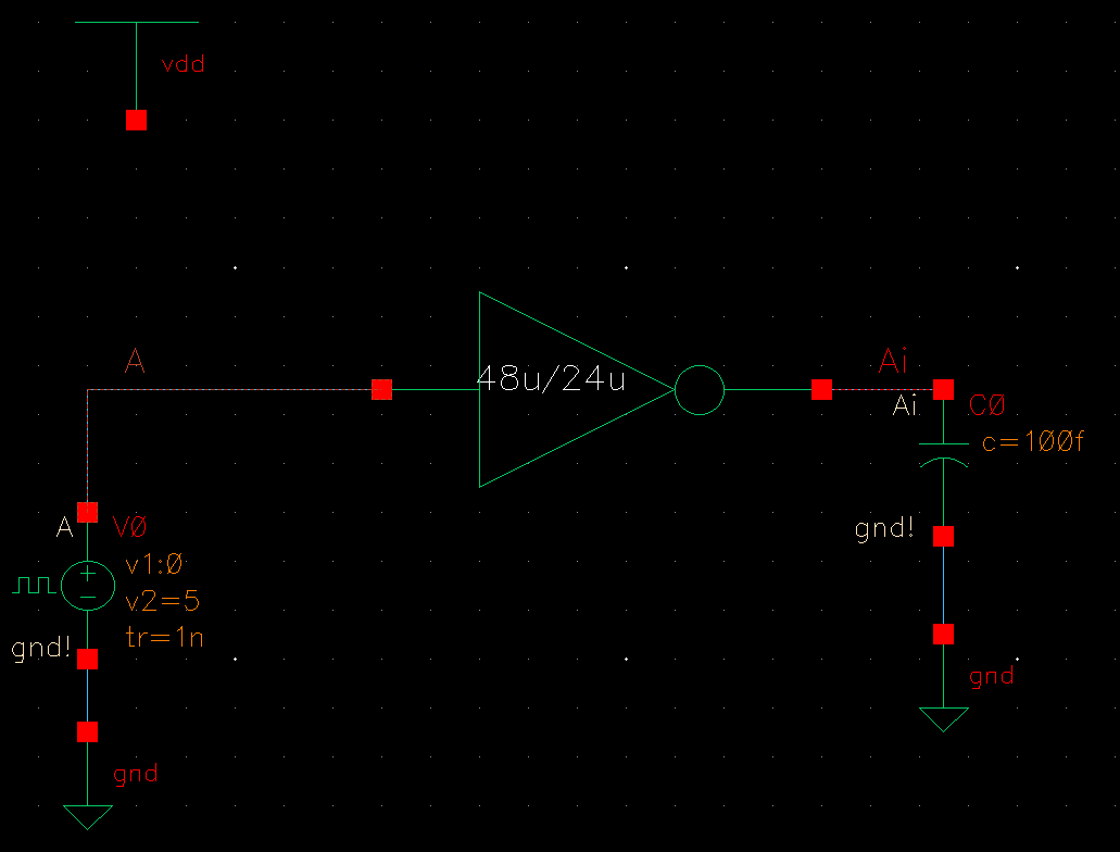
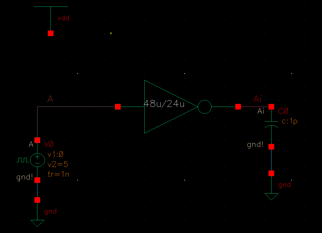
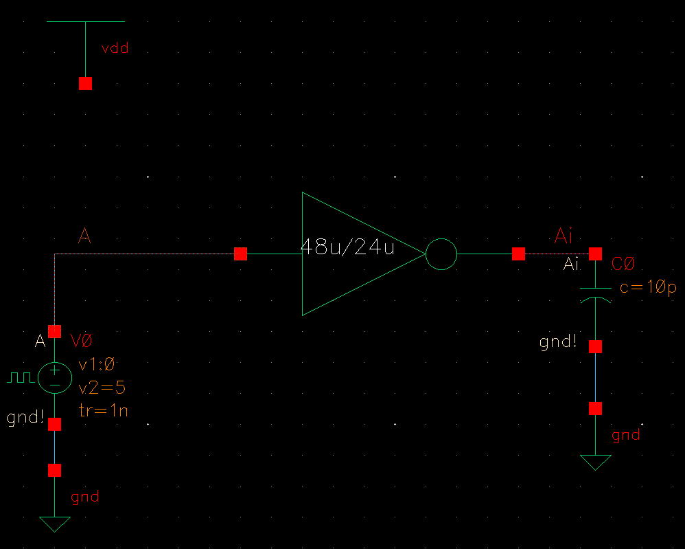
The next step in this lab was create a 48u/24u CMOS inverter. Below are the schematic, symbol, layout, extracted view, and LVS Results.
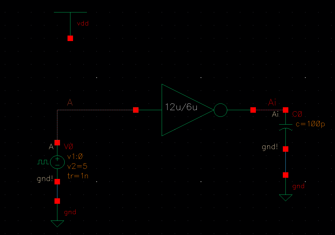
After
creating our inverters, we were tasked with simulating the operation of
each of them driving a 100 fF, 1pF, 10pF and 100 pF capacitive load. We
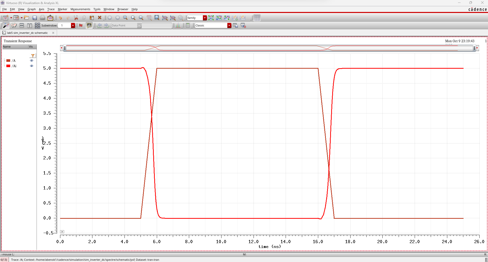
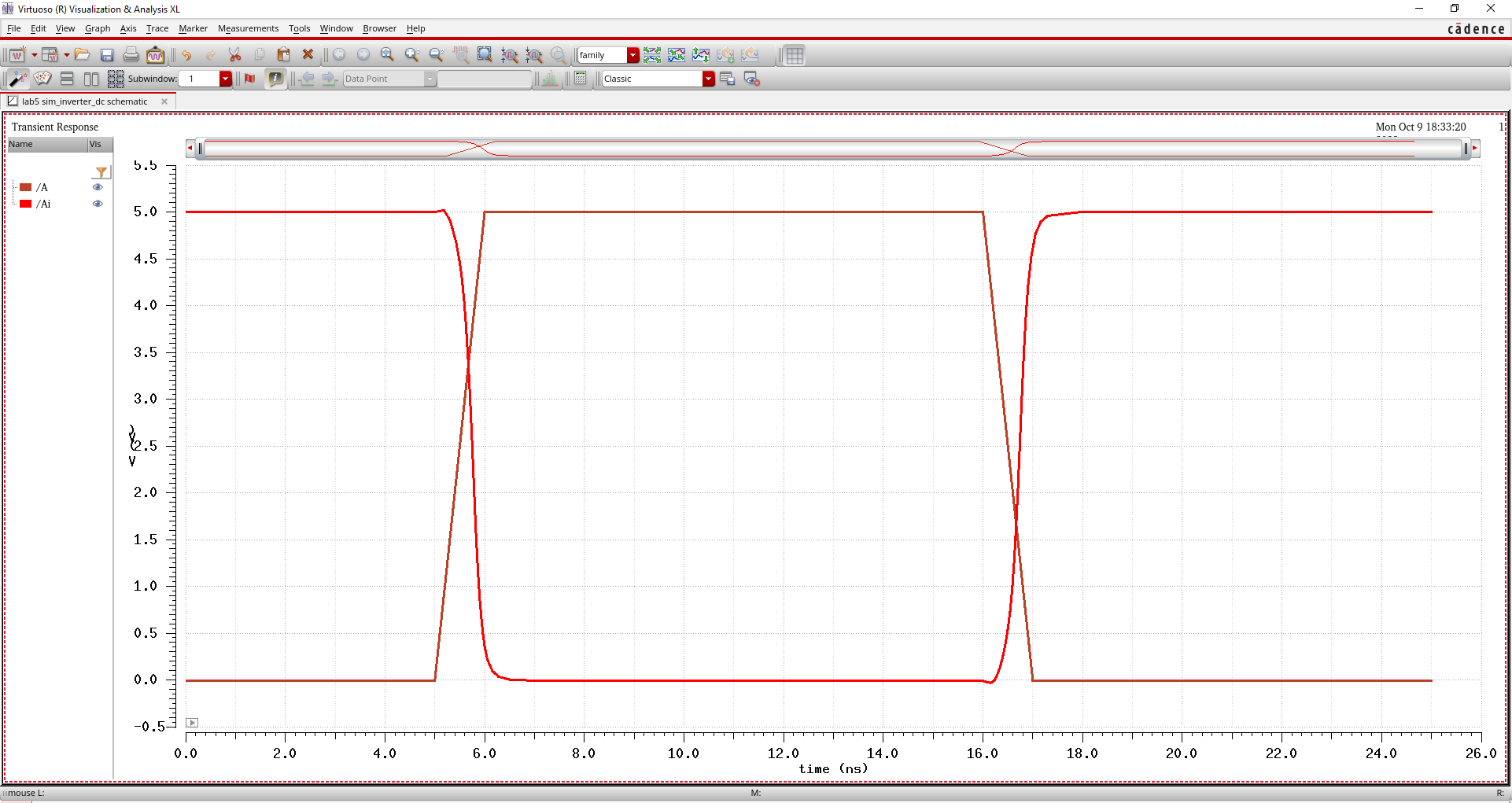
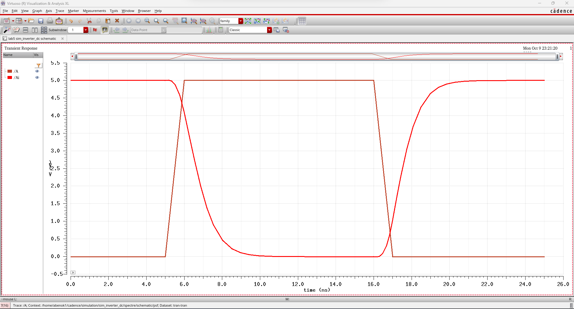
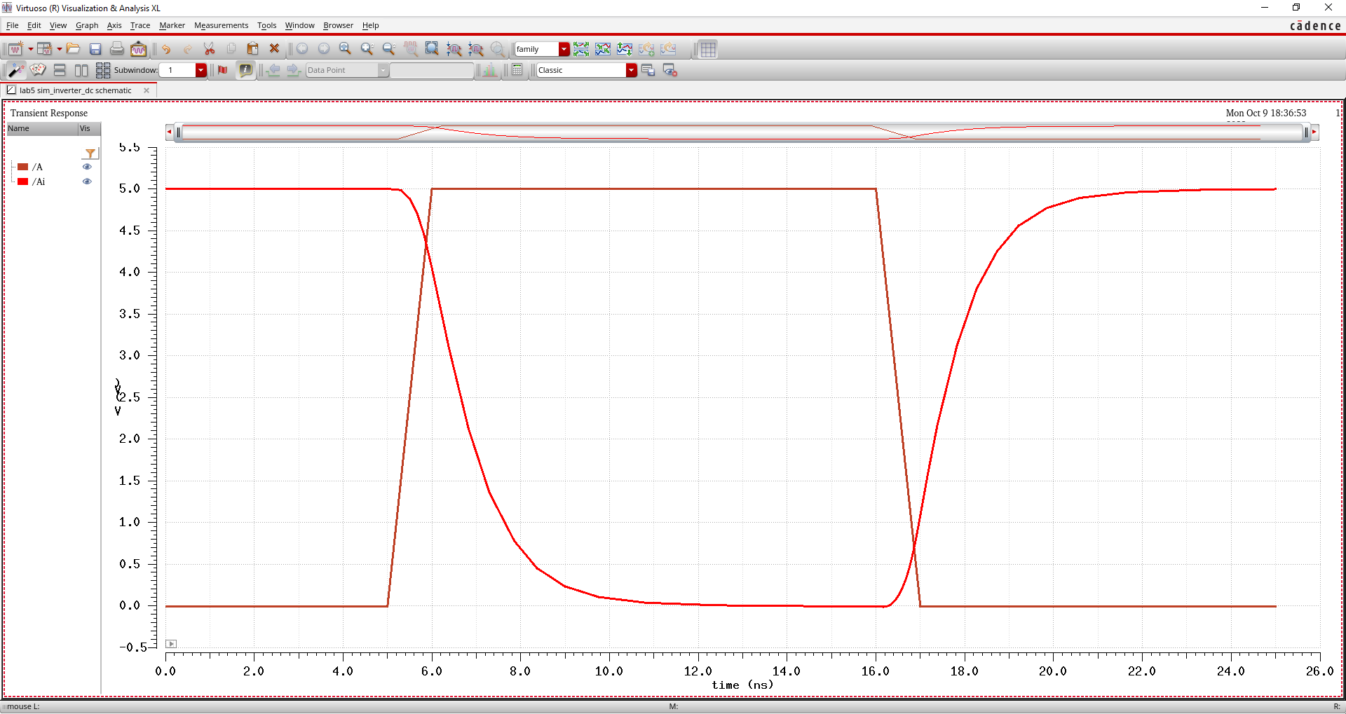
simulated each circuit twice, once using a transient analysis with Spectre and another time
using a transient analysis with Ultrasim, Cadence's fast SPICE
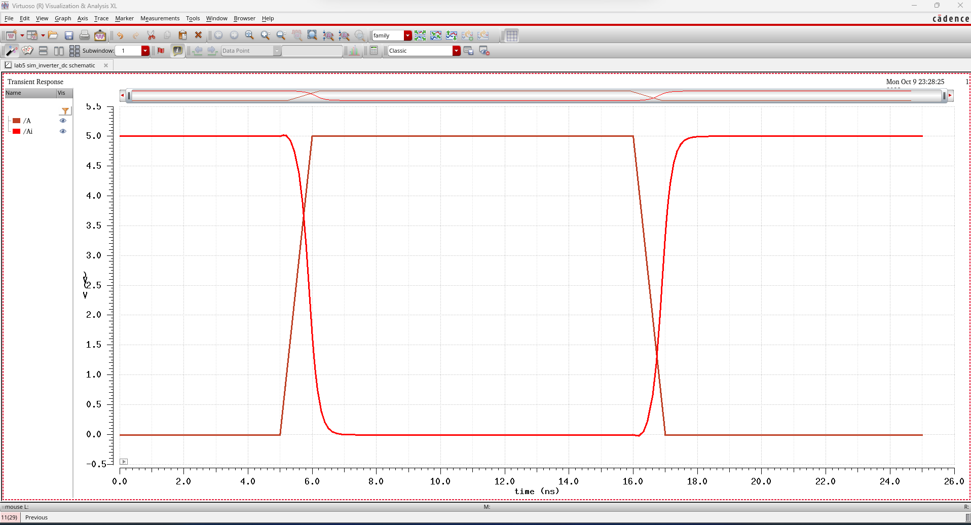
simulator. Below, I will label each circuit and paste both the transient
analysis using Spectre (left picture) and tran analysis using UltraSim
(right picture).
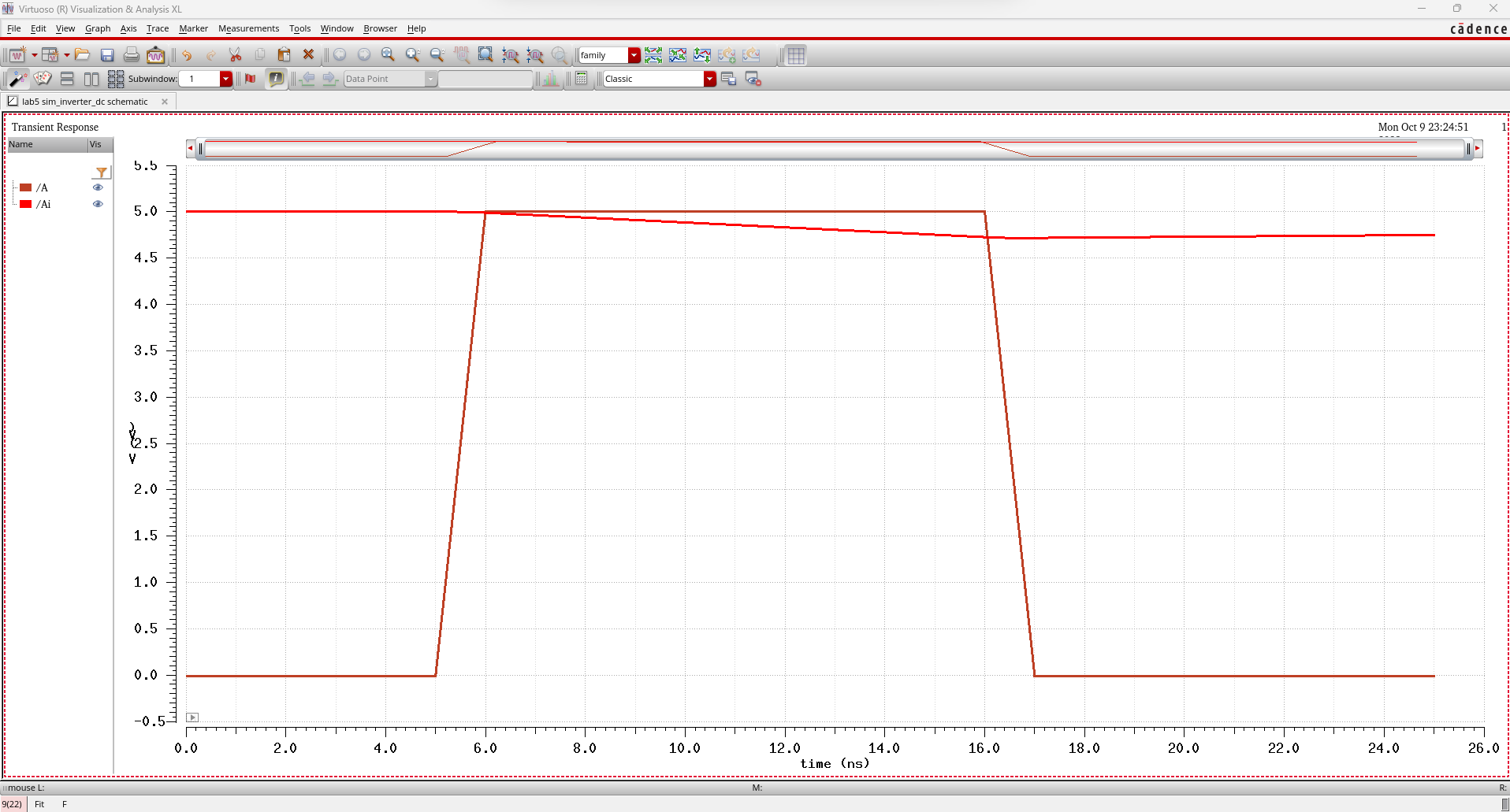
12u/6u with a 100 fF load:
12u/6u with a 1 pF load:
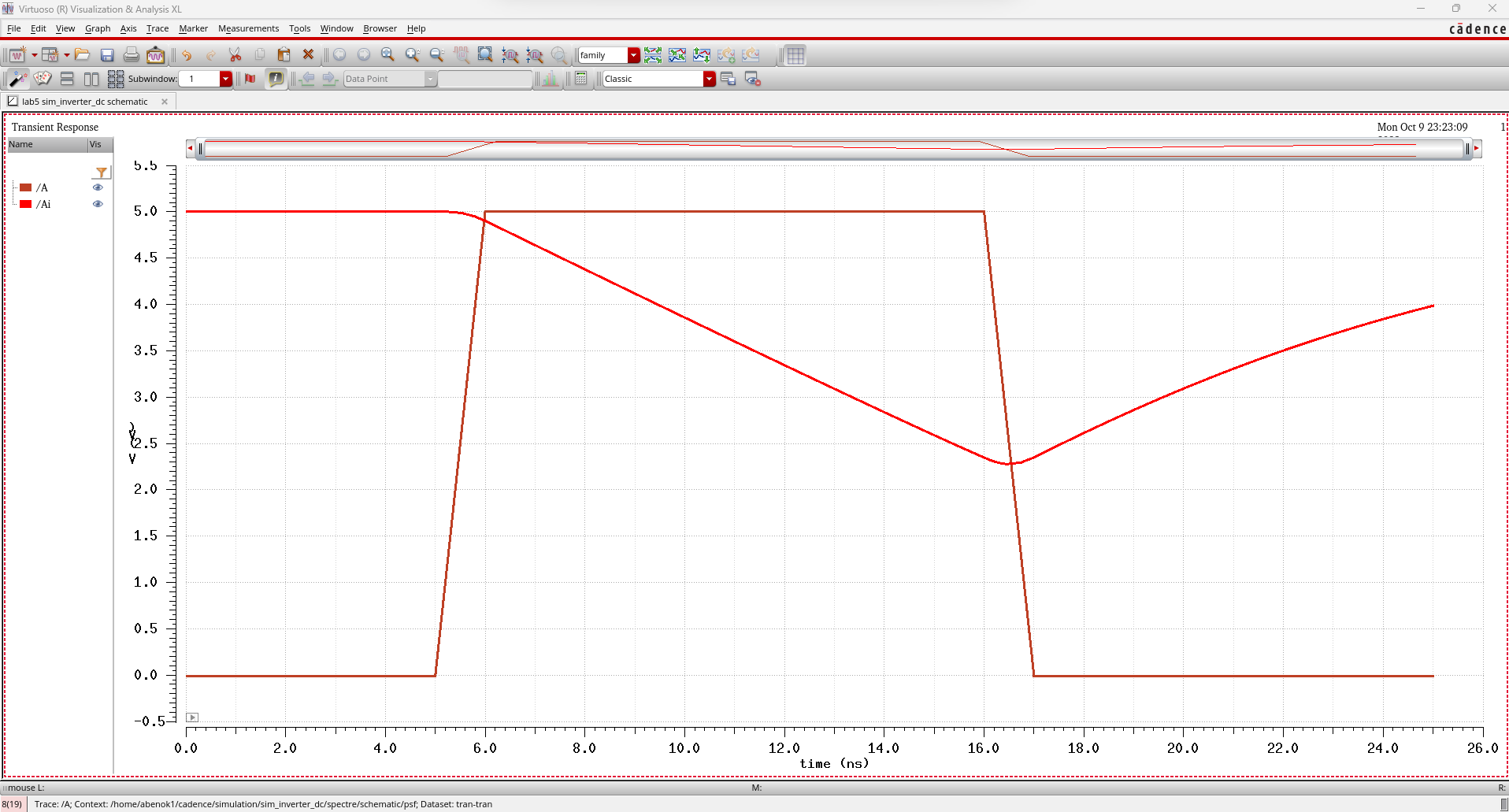
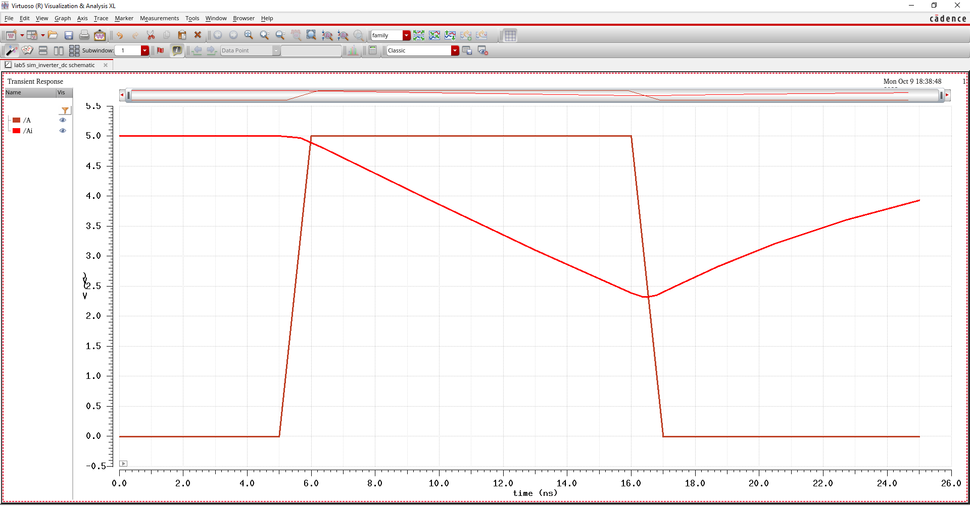
12u/6u with a 10 pF load:
12u/6u with a 100 pF load:
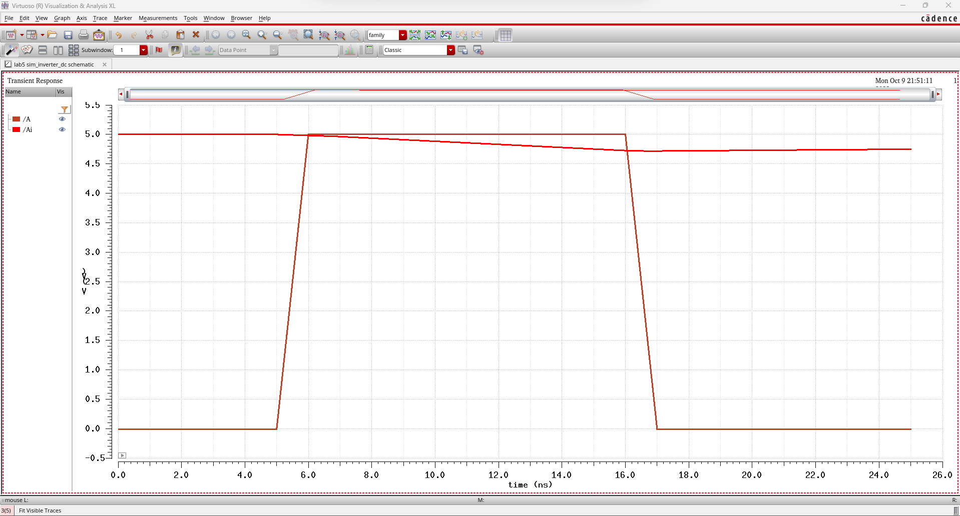
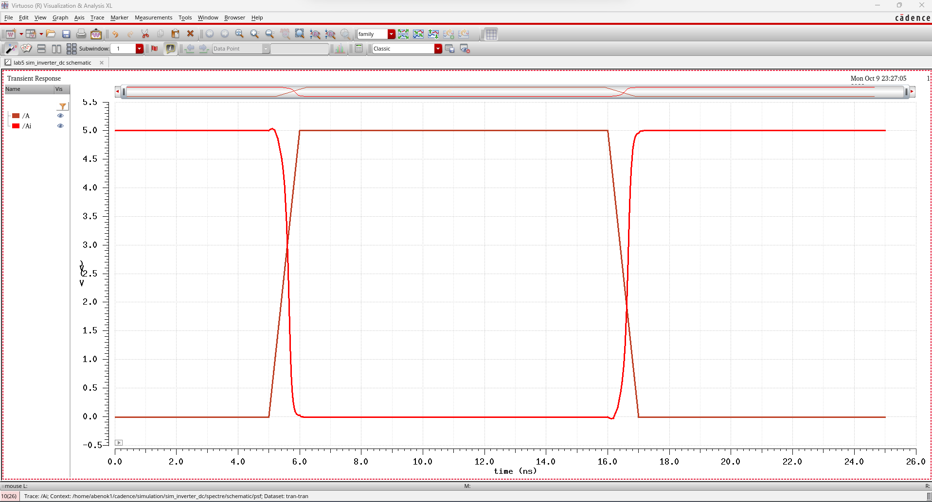
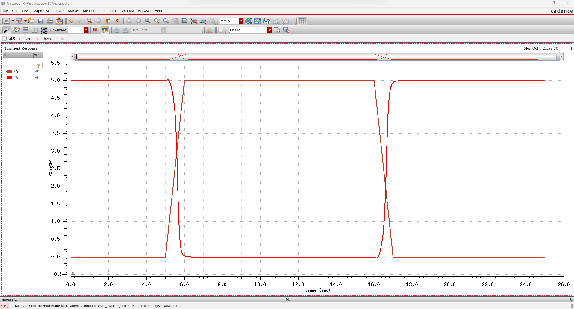
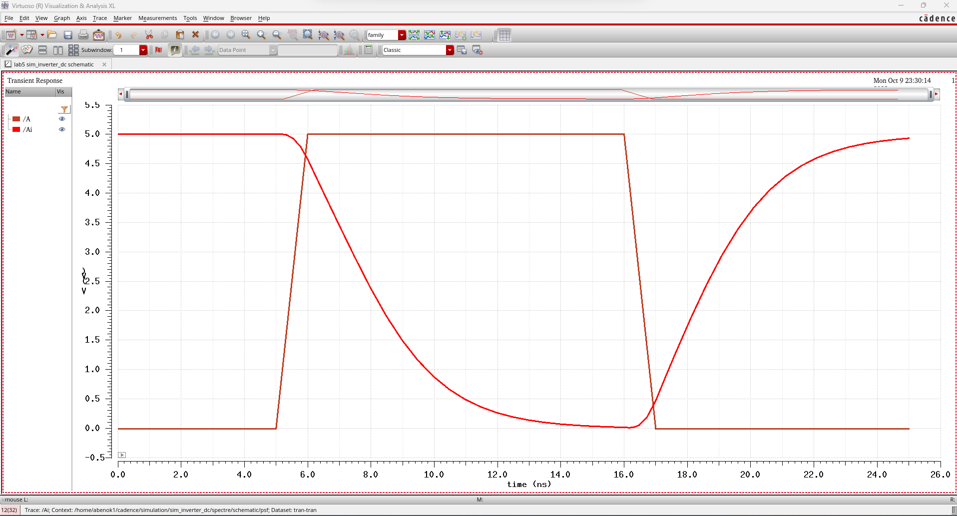
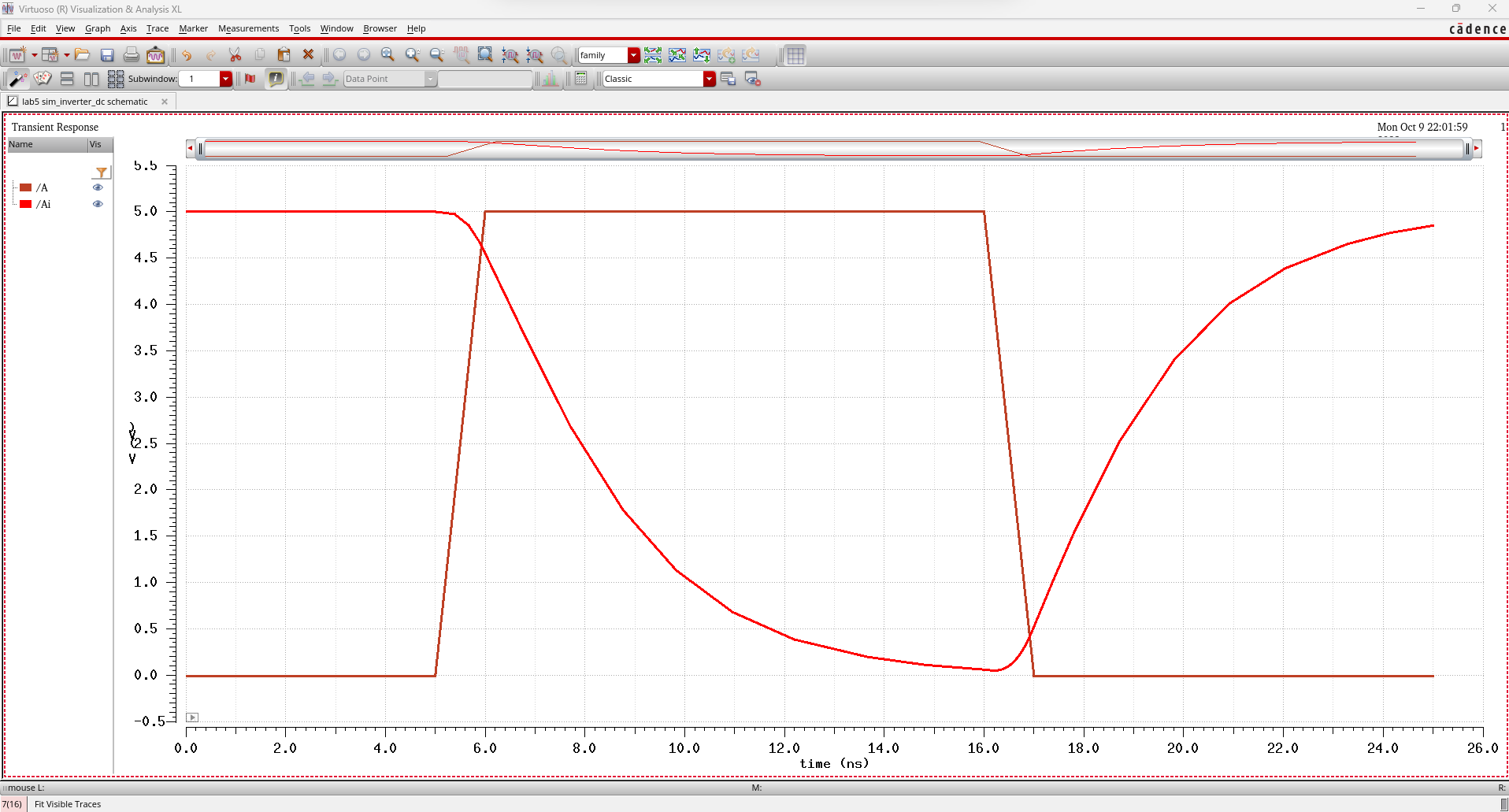
48u/24u with a 100 fF load:
48u/24u with a 1 pF load:
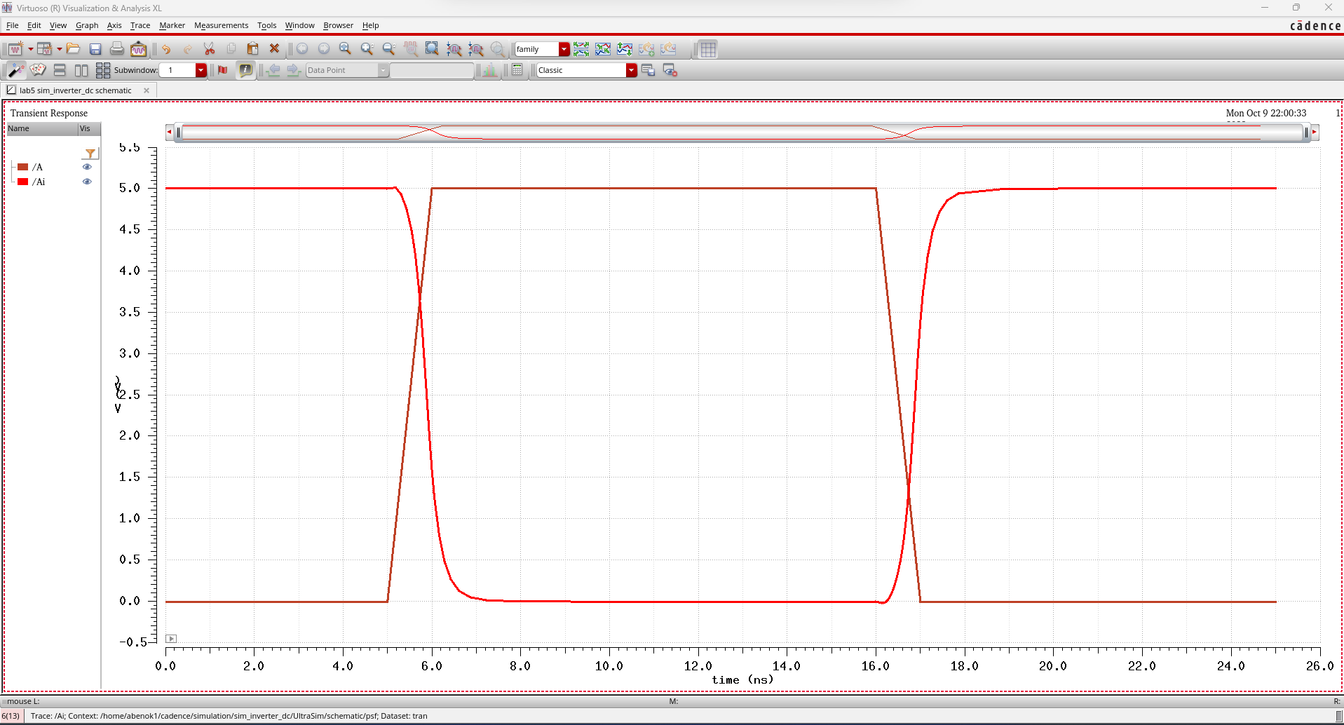
48u/24u with a 10 pF load:
48u/24u with a 100 pF load:
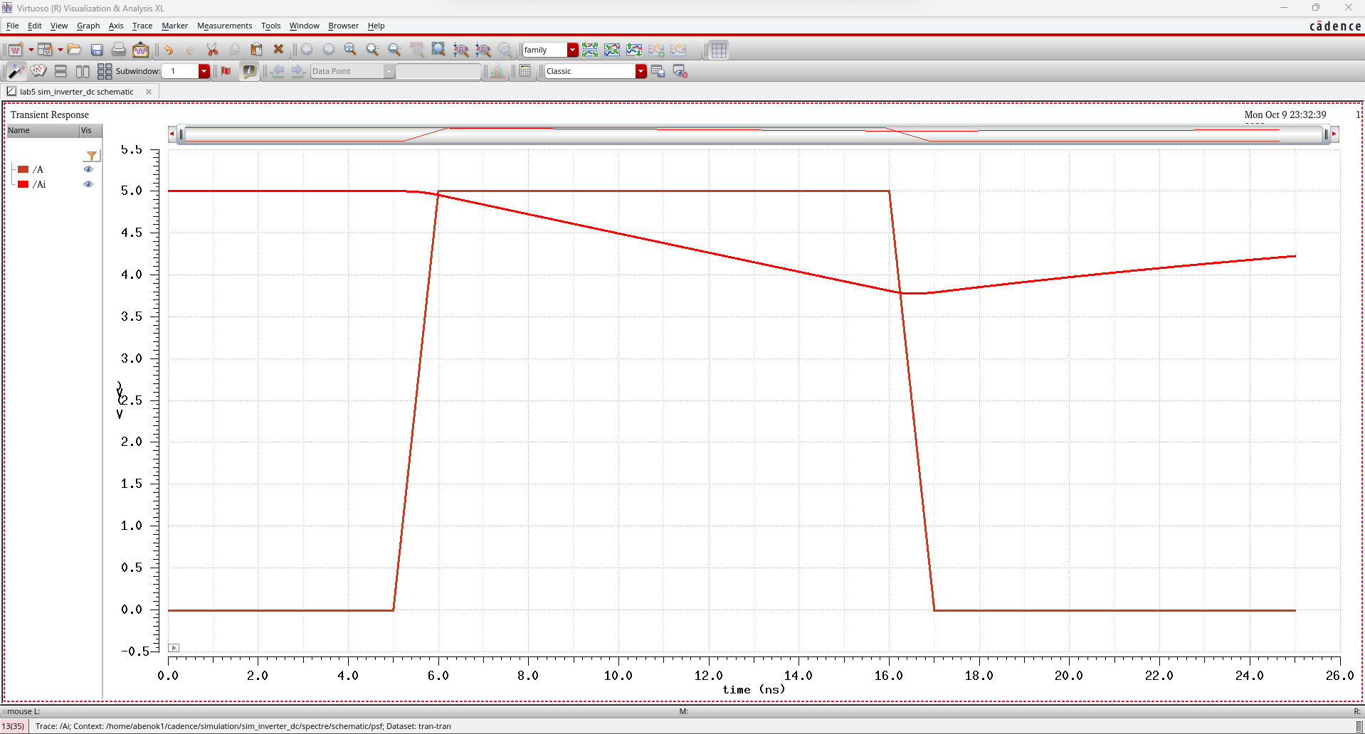
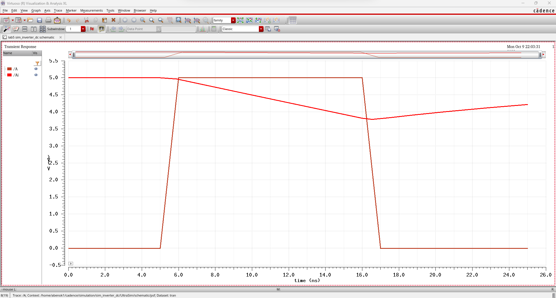
As
we can see from our results, our inverter works as we expected. When
the input is 0V, our output is 5V and vice versa. We also see that
there is a delay for the output to reach its final state. With
increasing capacitive load, we see that the delay increases. With the
48u/24u, we see that the transition happens faster because the larger
CMOS inverter has a decreased resistance. We also see slight variations
between our outputs from the Spectre and UltraSim SPICE models. As we
know, UltraSim is faster but at the cost of accuracy so we know that
our Spectre simulations are closer to real operation.
Zip File Containing CMOS Inverters and Simulation Circuit:
lab5.zip
Return to 421L Labs