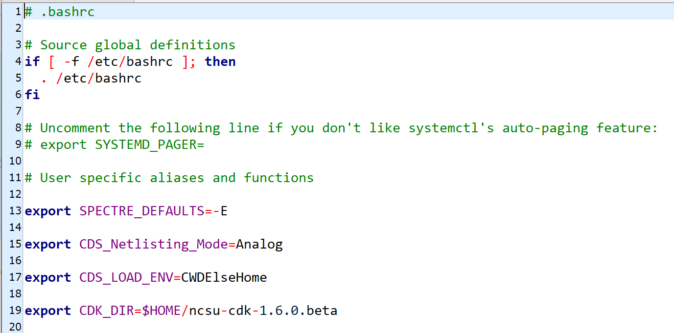
The first step in this lab was to setup the NCSU cdk. I downloaded the appropriate file from the NCSU website then extracted to the proper location. After extraction all that was left was to point our bashrc file to the location of the this file. Pictured above is a screenshot of the changes made to my bashrc file in order to point it to the location of my ncsu file.
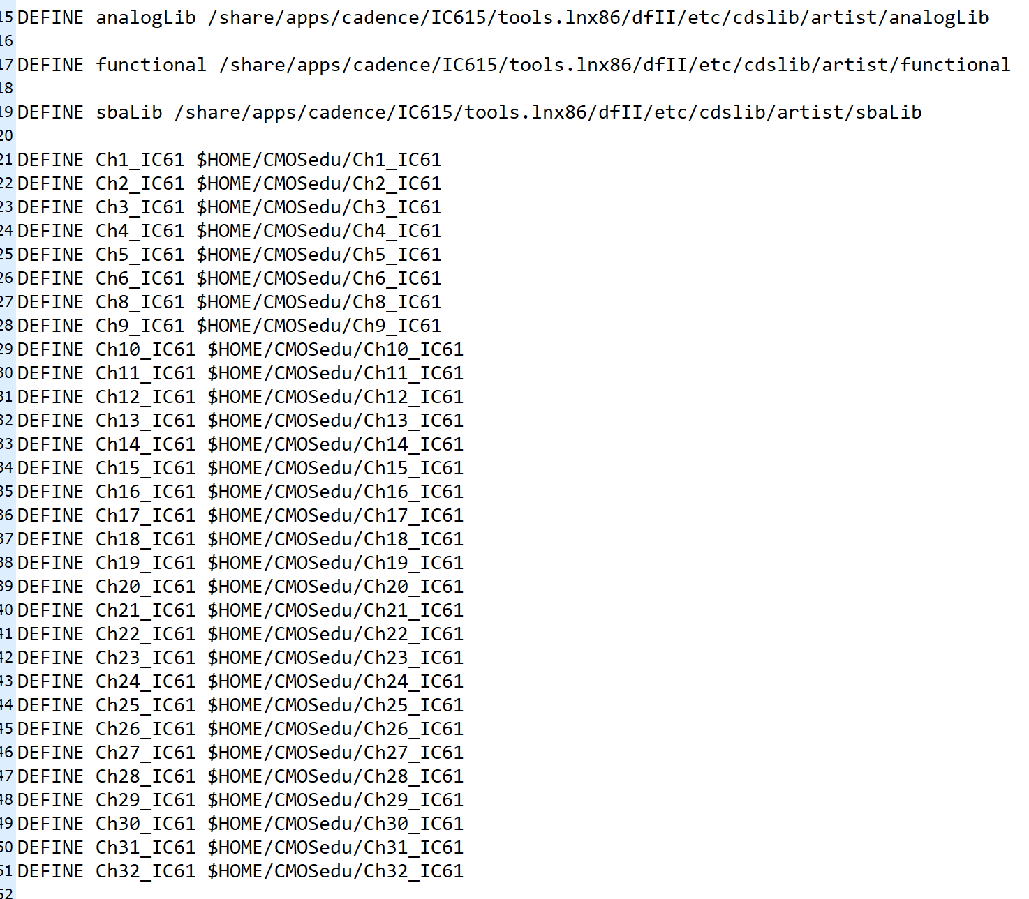
After setting up the ncsu cdk I next had to create the CMOSedu directory in my home folder then make certain files(cdsinit, simrc and cdsenv) hidden. This was done by simply adding a . to the start of the file names. Afterwards all that was left to do was point cdslib in the direction of the cadence libraries. This was done by editing cdslib file as shown in image above.
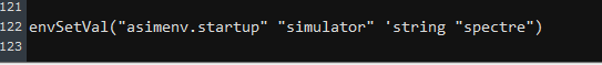
The next step was very important for improving speed. In this step I had to edit my cdsinit file in order to tell cadence to use spectre by default. This step saves me alot of time in the future because it sets our spice by default to spectre as opposed to having to pick it everytime I want to run a simulation. Pictured above is the change made to cdsinit.
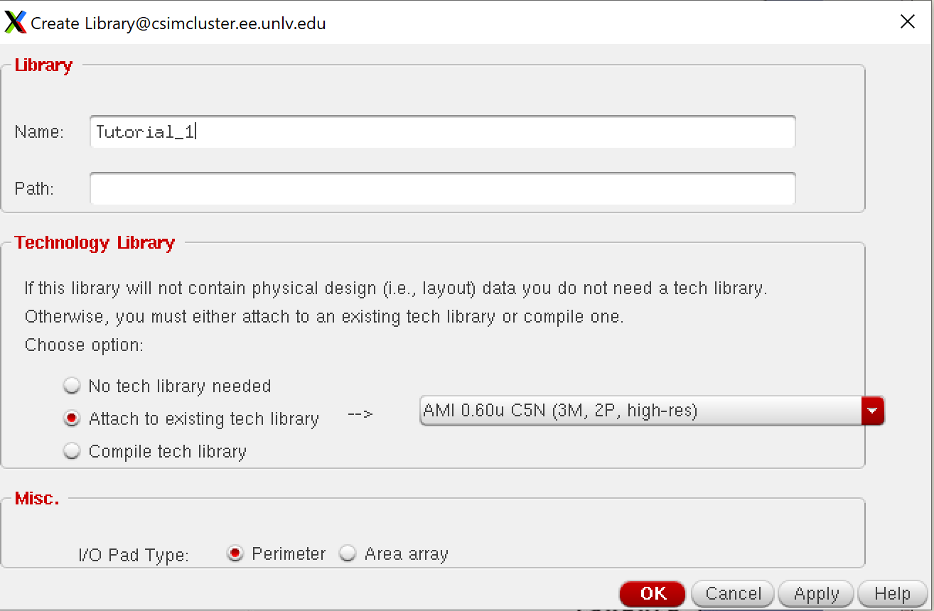
After finally completing all the prep work, I was now finally able to move on to finally starting up cadence. Before simulating, I had to setup a new cadence library for this lab. It wasn't complicated only important step was to specify that I would be using the AMI 0.60u C5N tech library. After doing this I was ready to move on. Pictured above is my library settings.
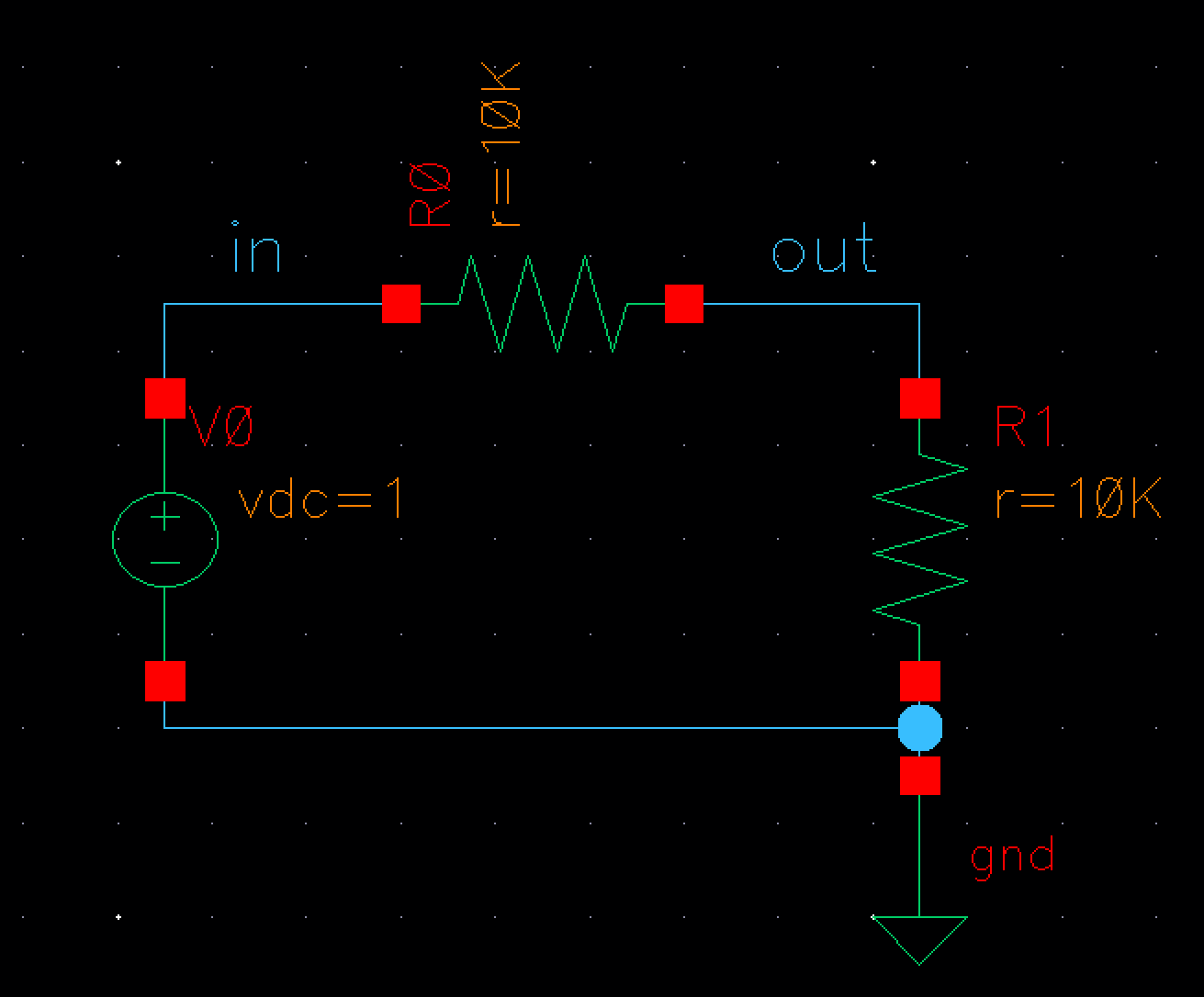
Since I now had my library setup I could finally create a schematic. Creating the schematic was intially difficult because it is a way more involved process than LTSpice was. The difficult came from the fact that we're using actual libraries and not just generic elements so we had to be sure to use the circuit elements from the right libraries. After figuring out the location of the proper circuit elements designing the circuit was just point and click like LTSpice.
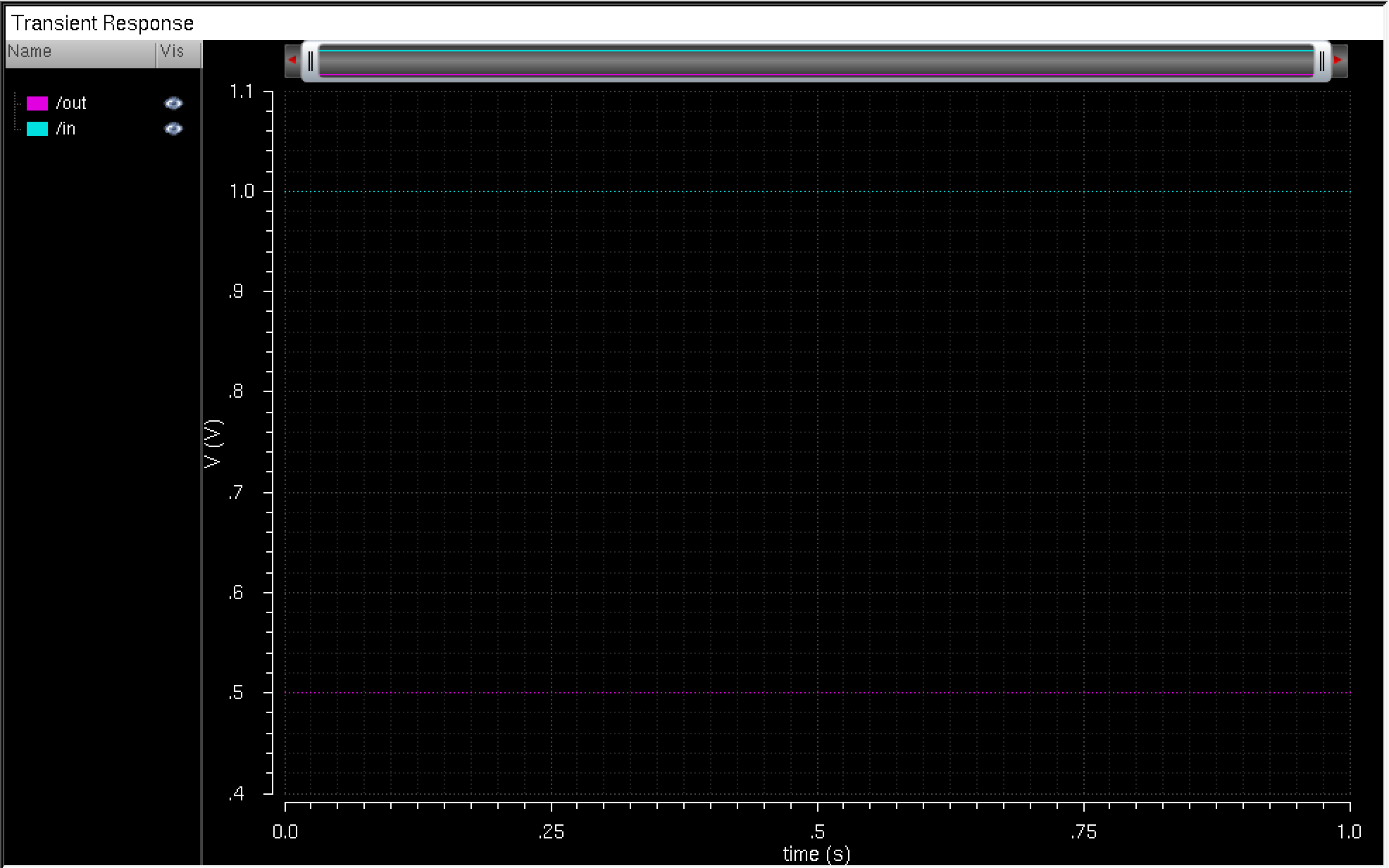
Since I completed desiging my circuit I was no ready to move onto the next step which was simulating my circuit. The tutorial showed my how to tell cadence that we would be using spectre for simulation. Luckily, this step was not necessary since we had previously made changes to our cdsinit file so cadence already knew that I would be using spectre to simulate my circuit. After this I had to specify what type of simulation we would be running(in this case transisent) and choose my nodes that I want to know the output of. Afterwards, I just clicked run and a plot was generated of my the voltages of my nodes over a 1 second interval.
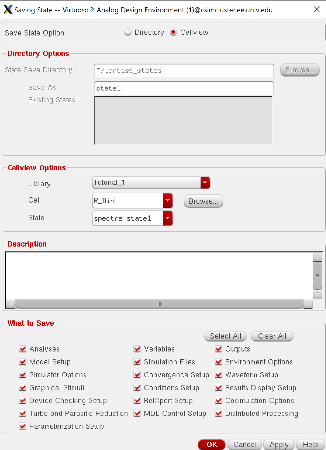
Finally the final step of lab 1 was to save my state for the future if needed. This was simple enough, I just had to go to save state and change the save state option to cellview and my simulation was saved for future reference.