Lab 5 - EE 421L
Author: Edgar Amalyan
Email: amalyane@unlv.nevada.edu
Date: 10/07/2020
Goals:
This lab focuses on the layout and simulations (IV curves) of NMOS and PMOS transistors.
Prelab
Note: Click on pictures for larger views.
Tutorial 3
Here we go through the creation of a CMOS Inverter (NOT Gate).
First
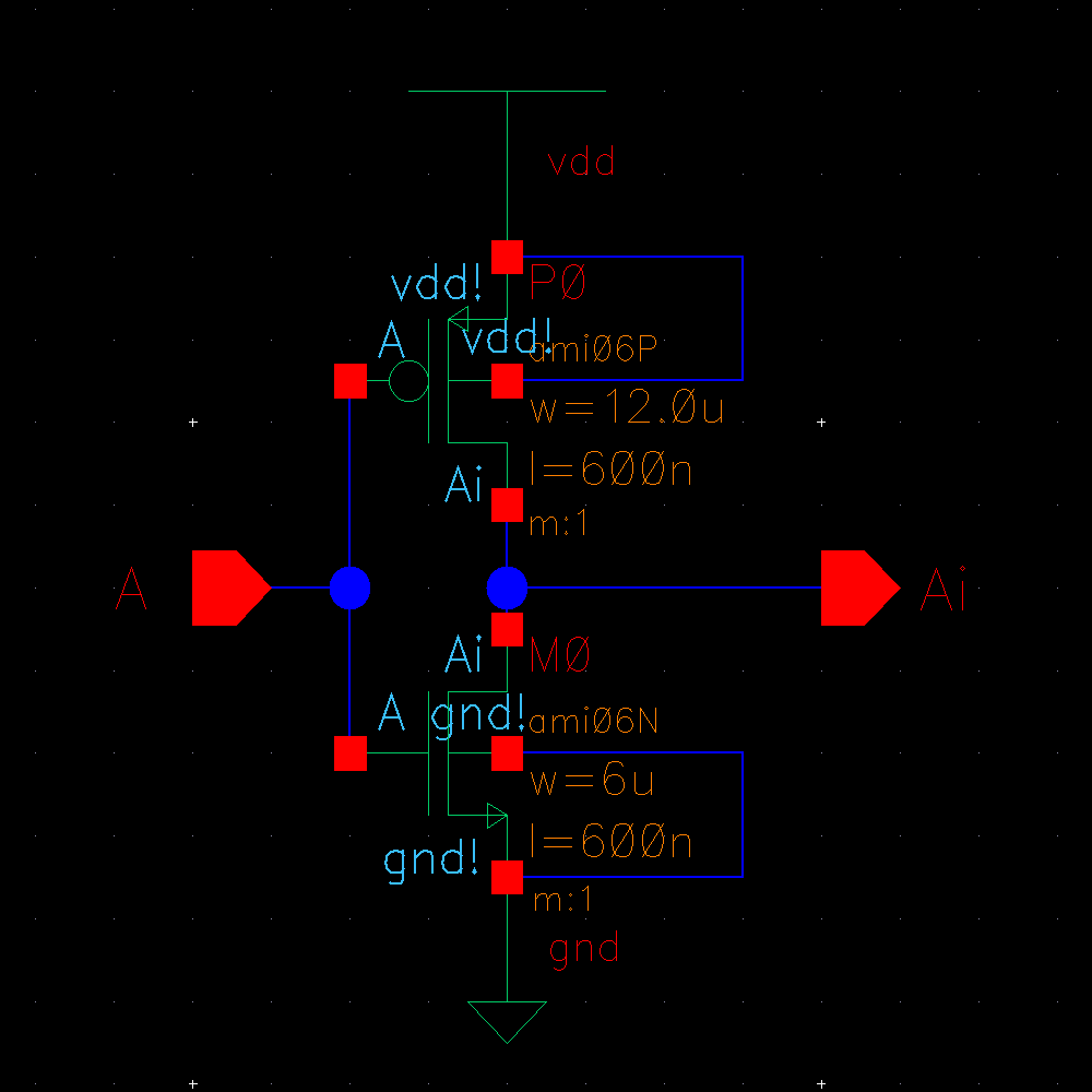
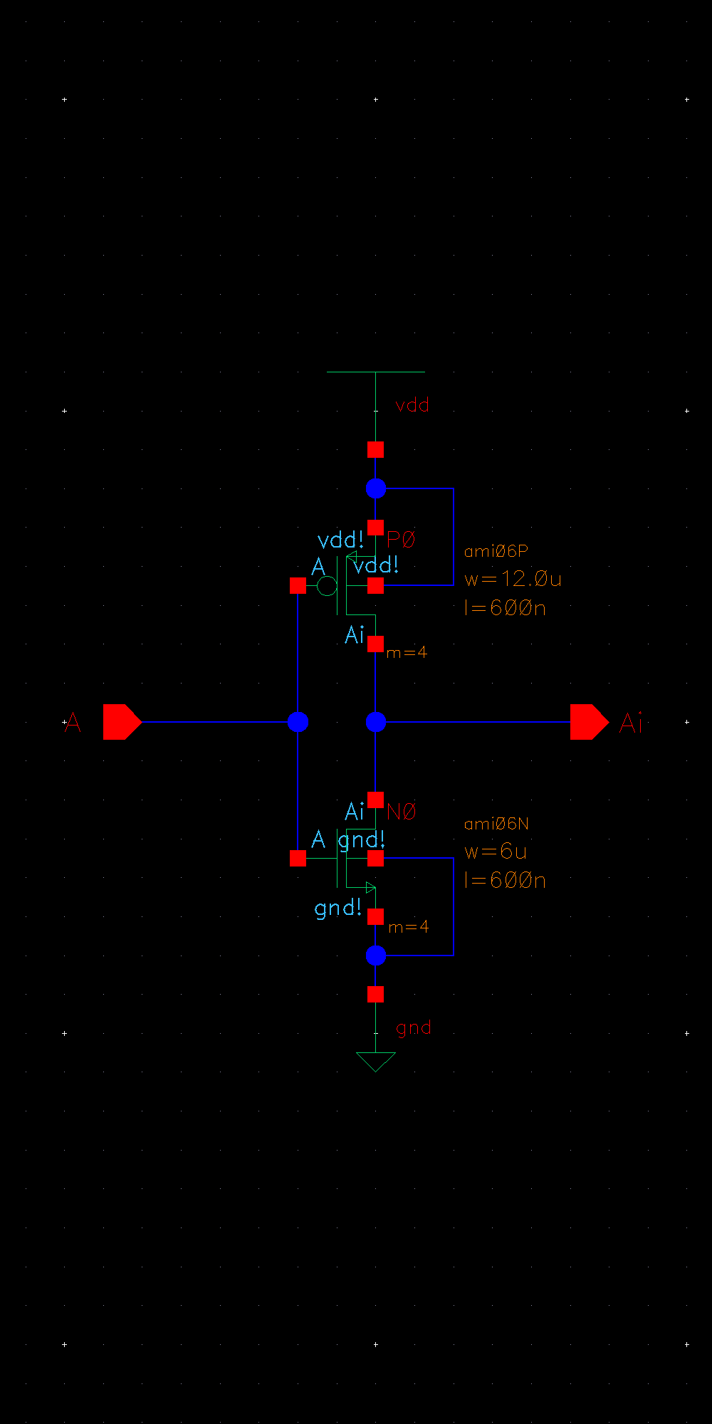
we draw the schematic for the inverter. An inverter consists of an PMOS
connected in series with a PMOS. When the input is 0, the output is 1,
and when the input is 1, the output is 0.
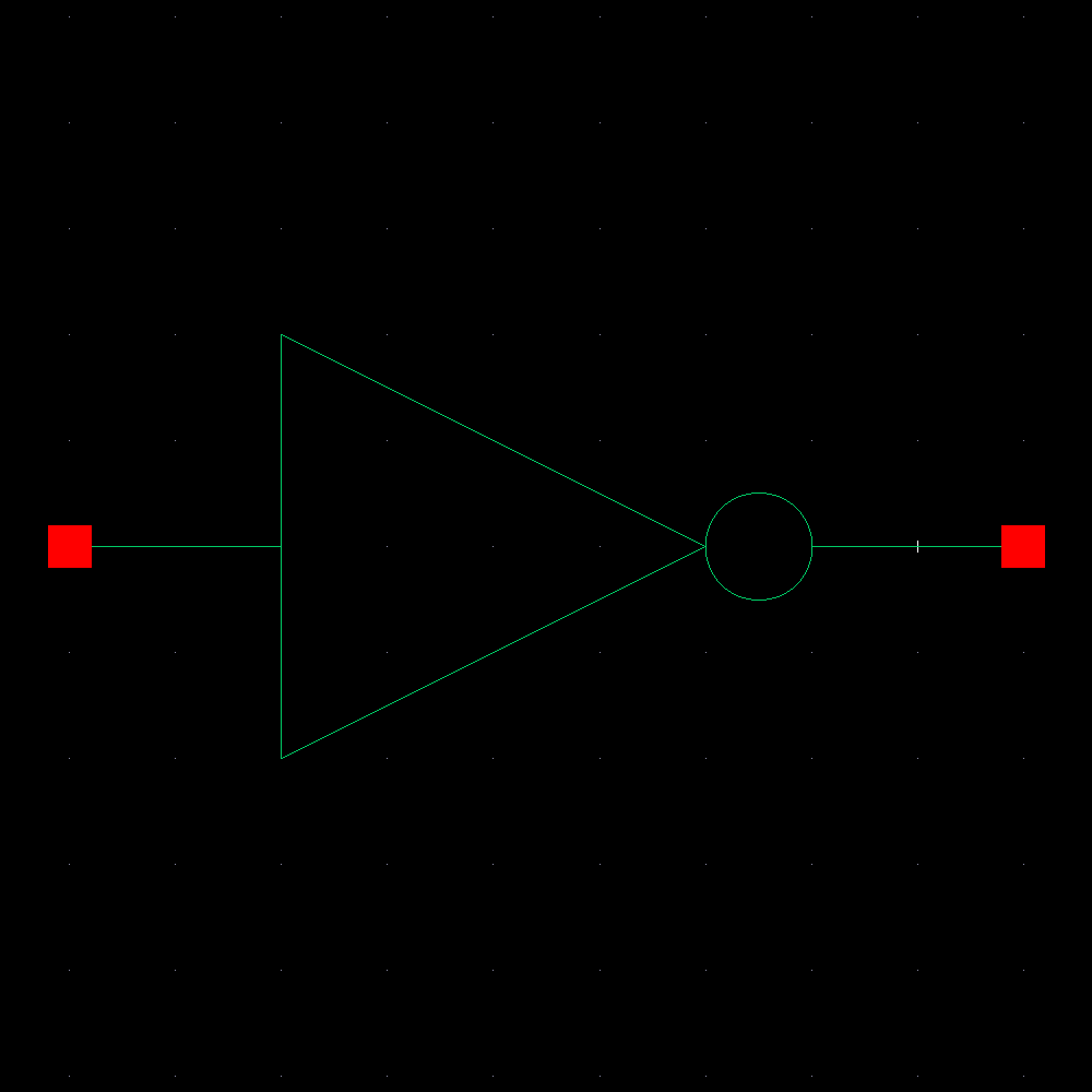
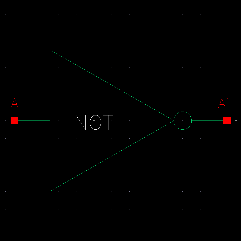
Now we can create a symbol for the our inverter from the schematic.
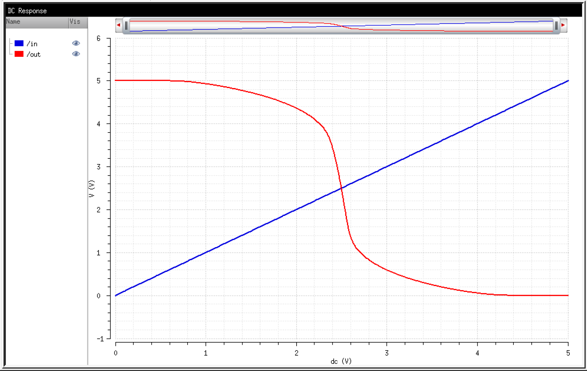
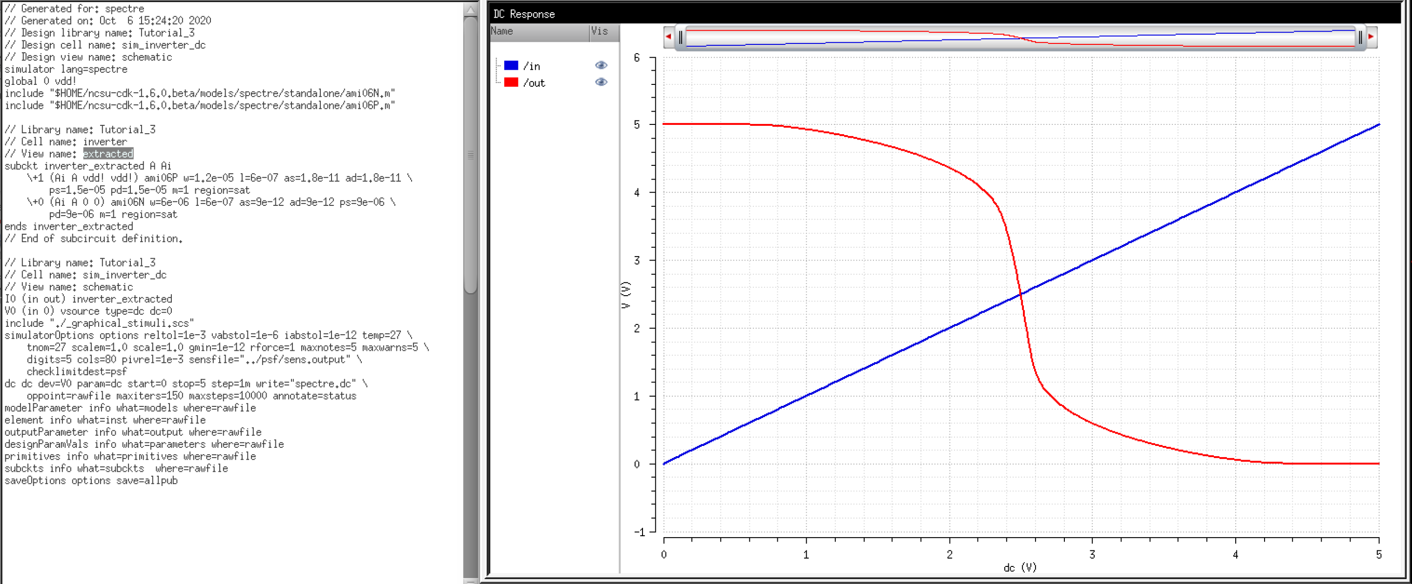
We can go ahead and simulate the inverter to verify its operation.
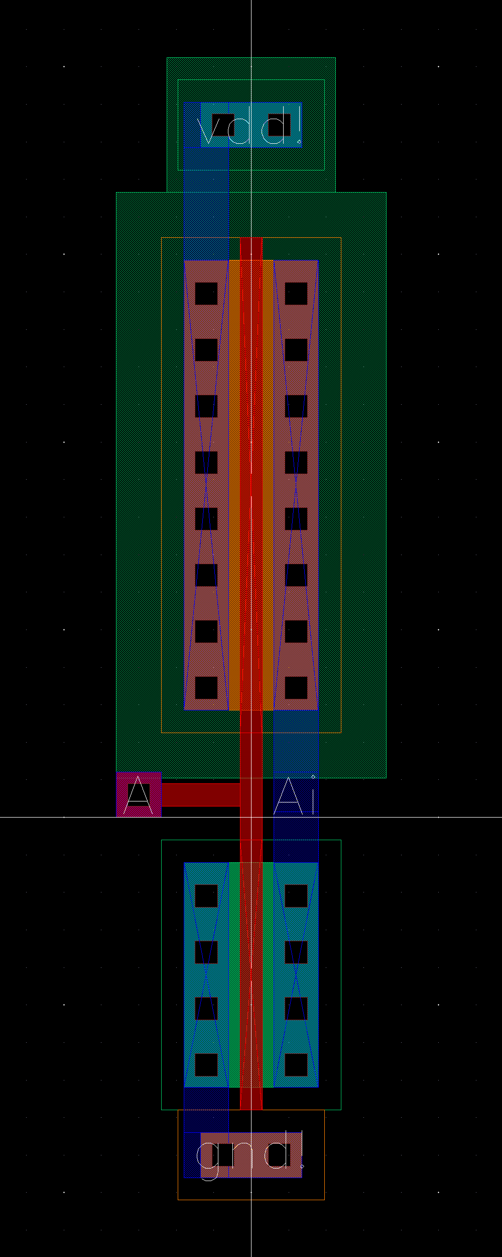
Now
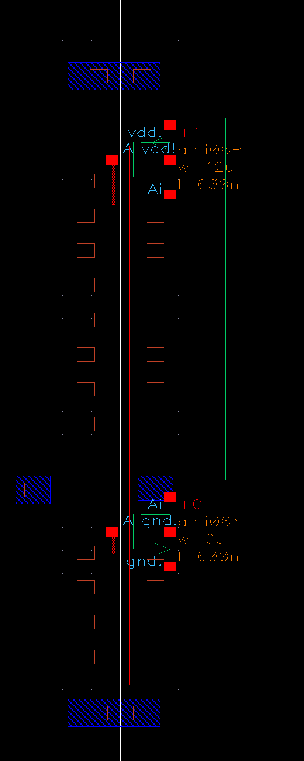
we can move on to the layout. As mentioned, the inverter is a PMOS in
series with a NMOS. We need to implement this in our layout by making
the appropriate terminal connections.
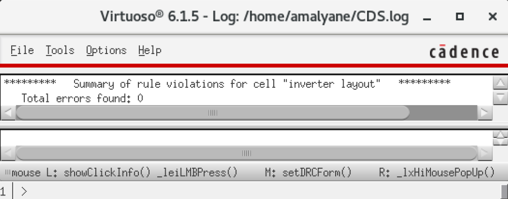
At this stage we should DRC our layout.
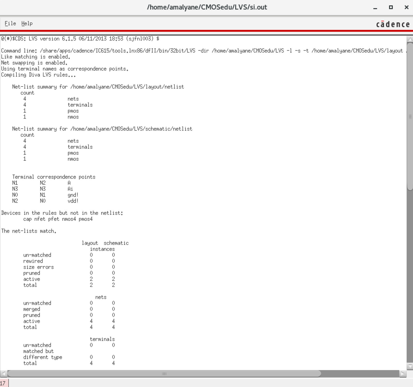
We extract the view to run the LVS.
We run the LVS.
We can now simulate the extracted view.
Lab
The lab is similar to the prelab.
Inverter - 12u/6u
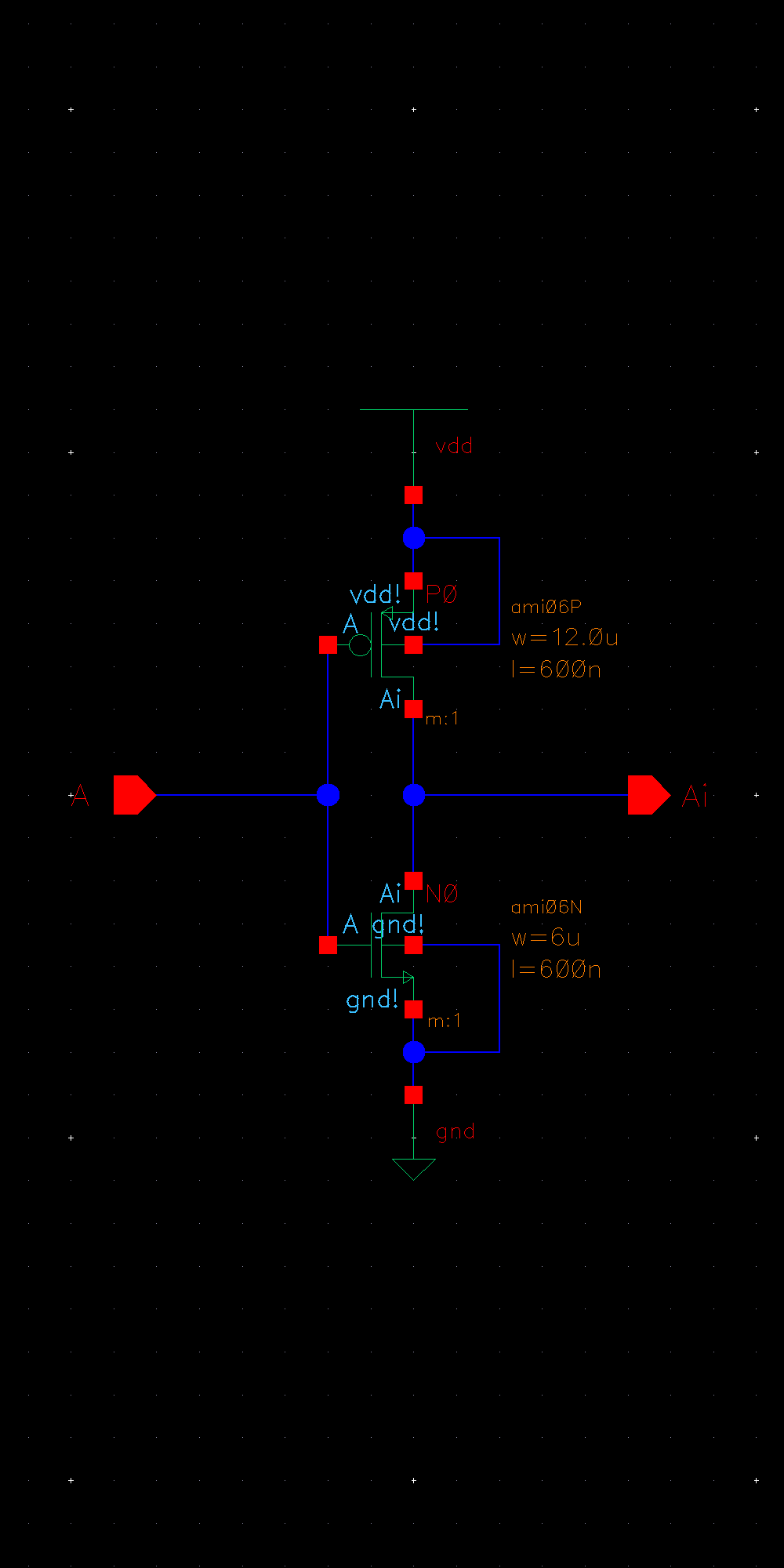
First we will create a 12u/6u inverter.
We start with the schematic.
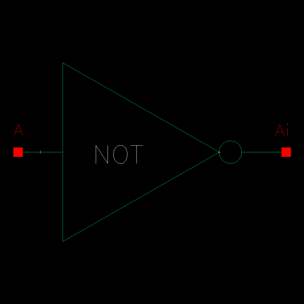
We create a symbol.
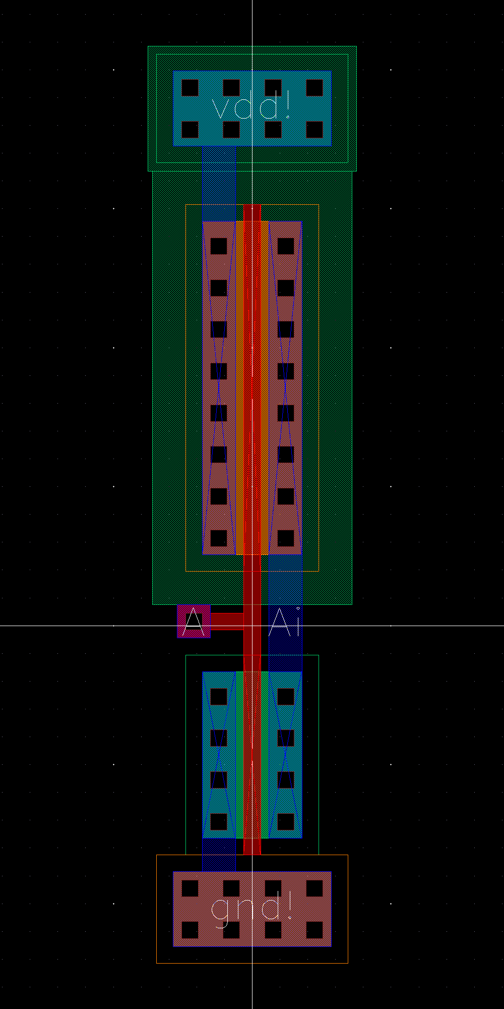
We start the layout.
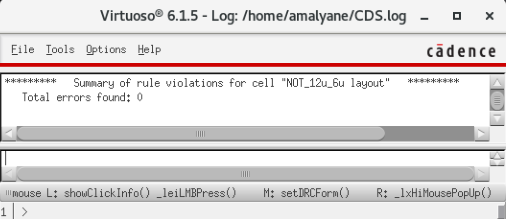
We DRC.
Extract.
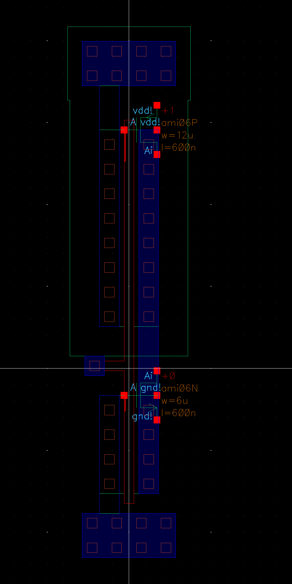
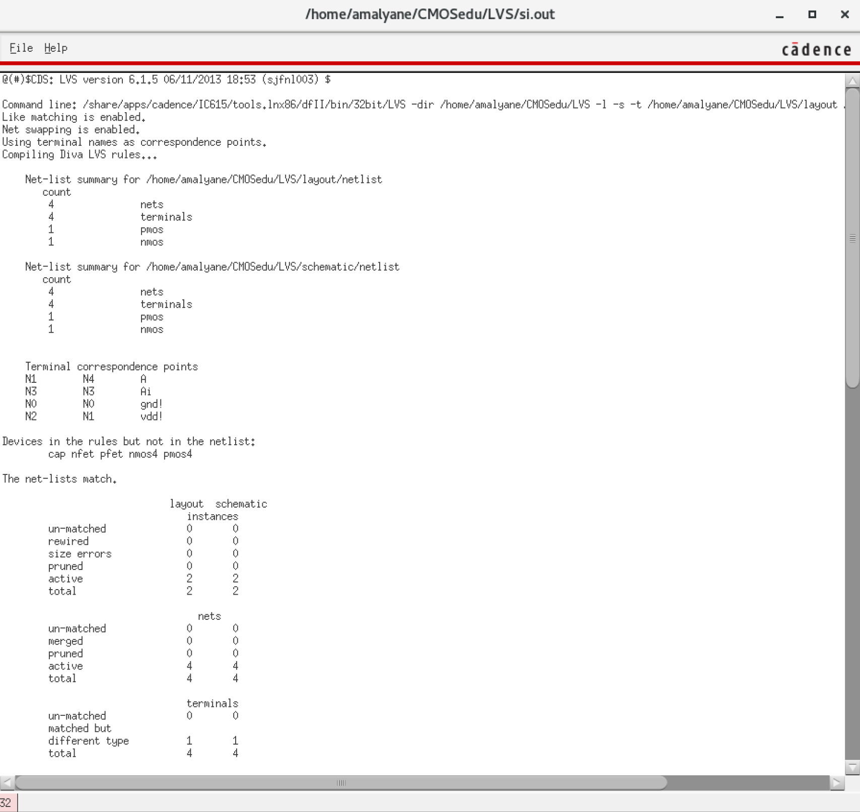
LVS.
Create a schematic to simulate the inverter we just layed out.

The
operation of a NOT gate is obvious, 0 in 1 out or 1 in 0 out. To
demonstrate the actual differences between how an inverter is
physically designed, we can add a capacitor at the output. The effects
will soon become clear.
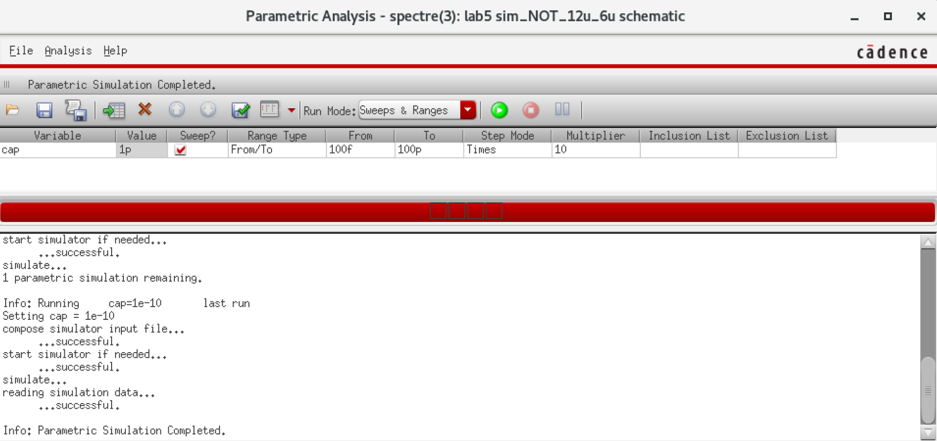
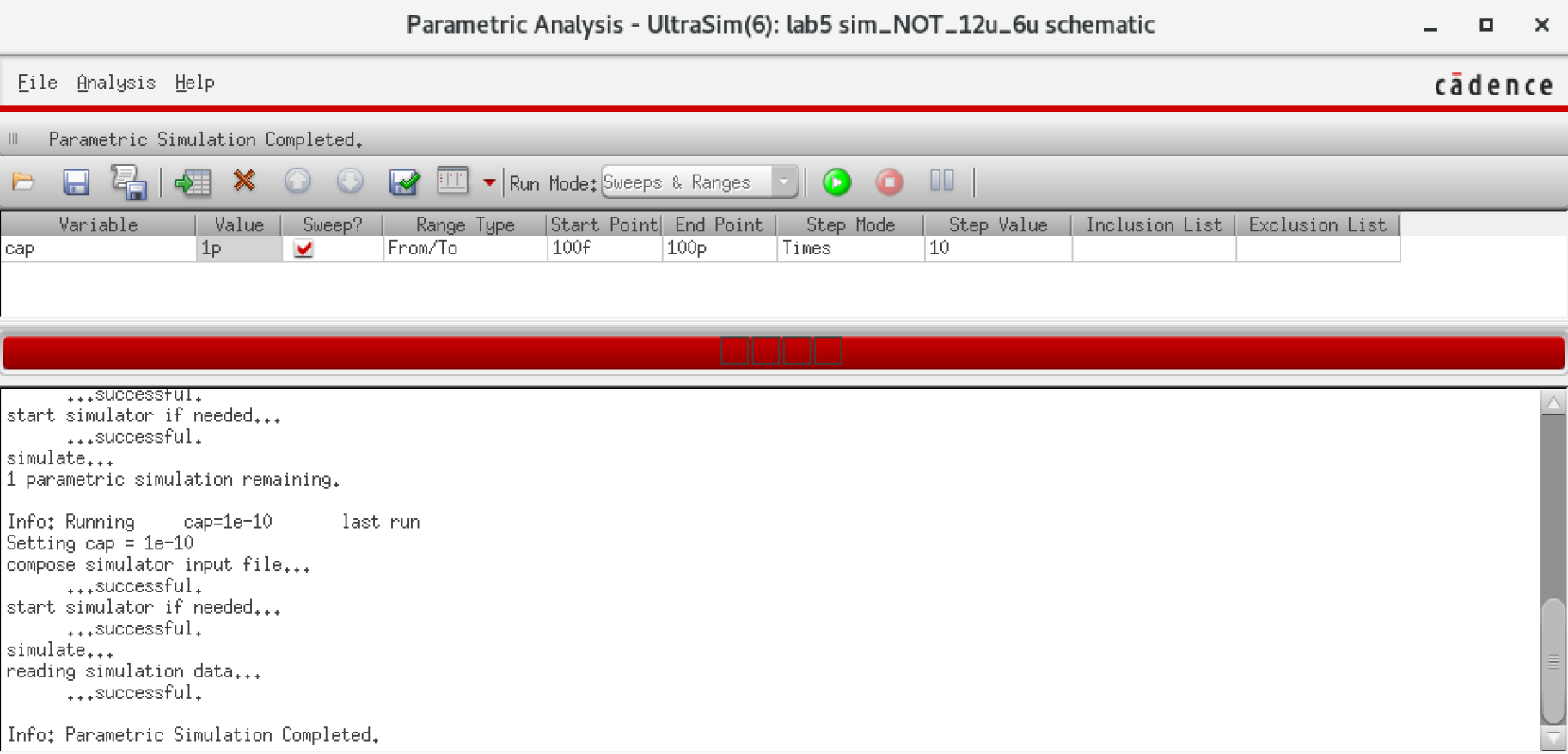
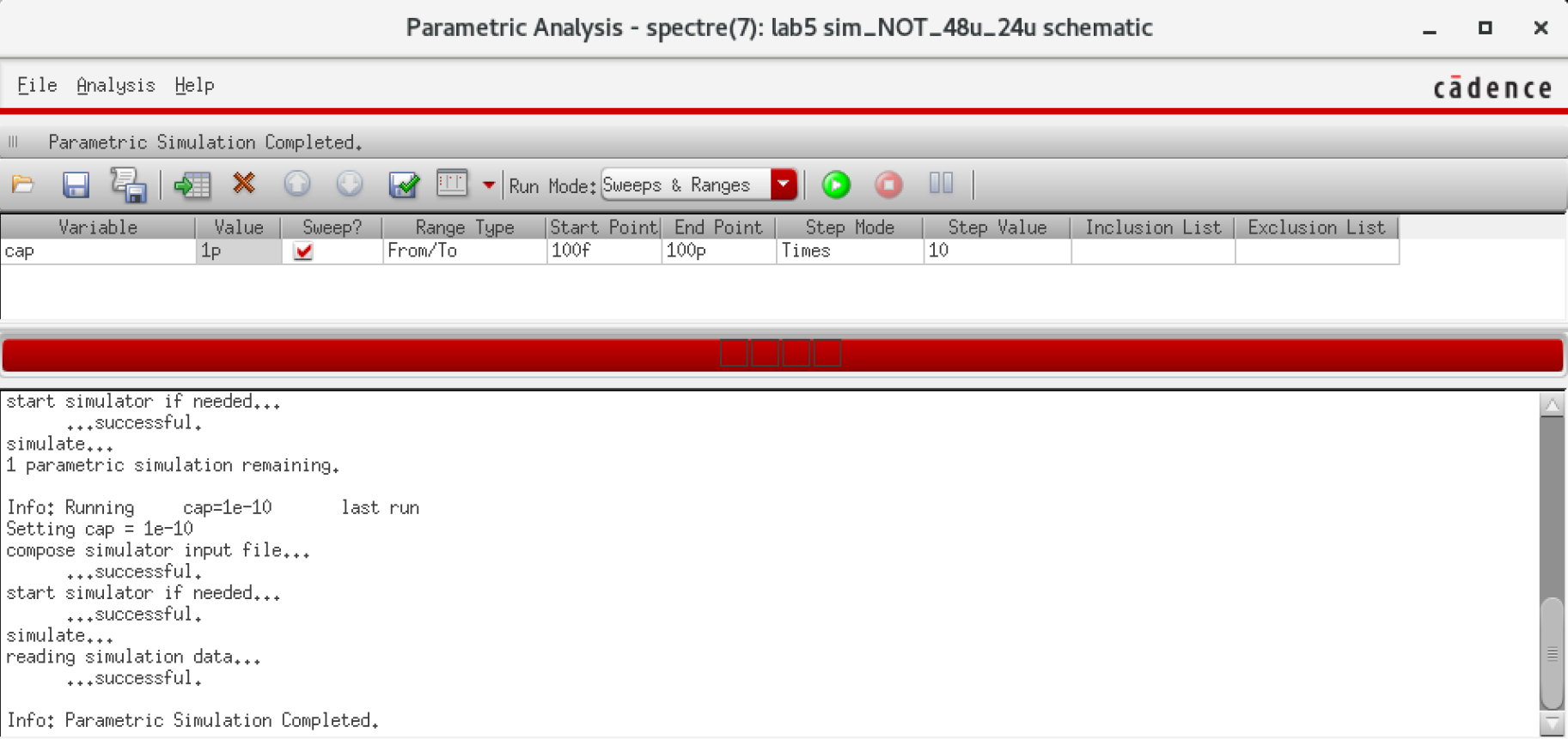
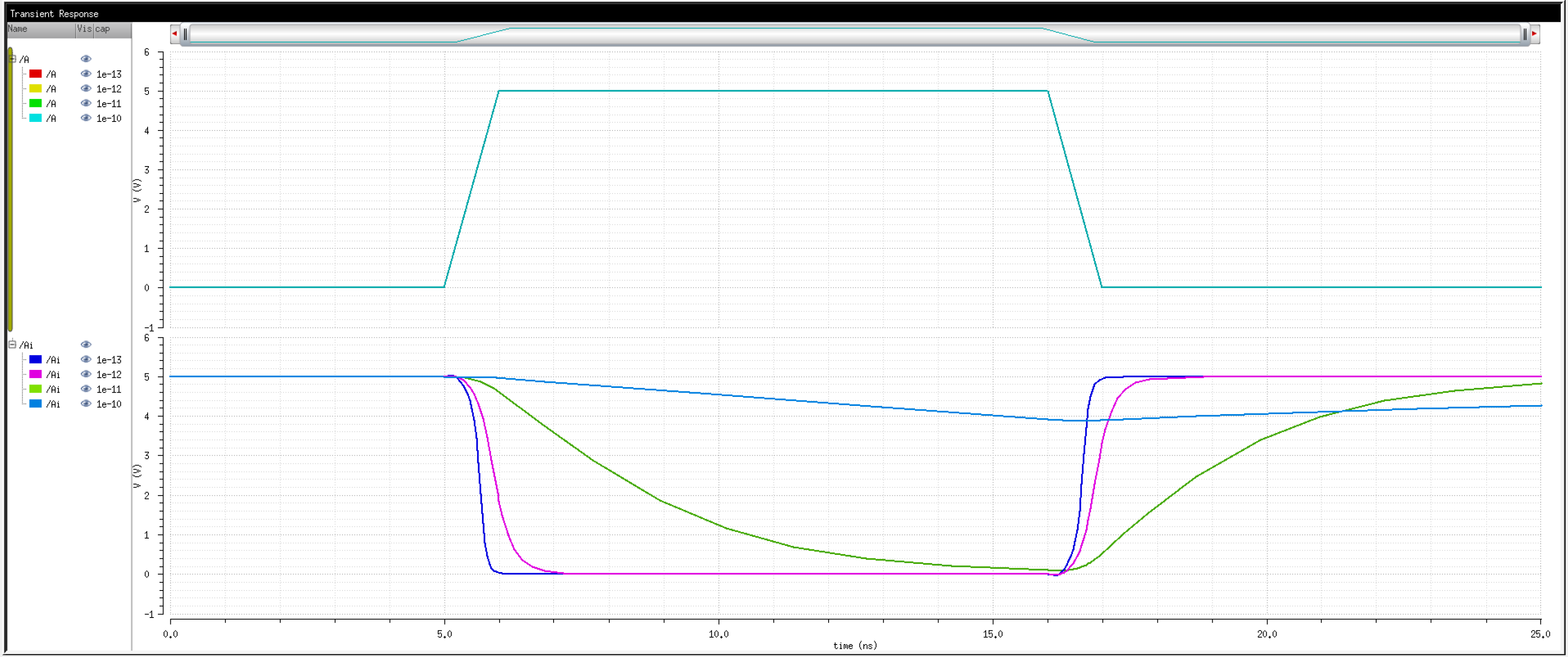
We can vary the value of the capacitor
from 100fF to 100pF in 10x steps. Instead of simulating 4 different
times, we can just run a parametric analysis.
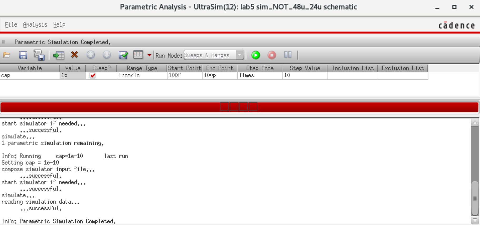
All
simulations thus far have been done using the Spectre tool in Cadence.
There are other simulation programs available, one of them being
UltraSim. Ultrasim can give us quicker results (for Transient Analysis)
with less accuracy. Let's try it out.
Note:
Make sure you to save states and the parametric analysis to avoid
having to redo it everytime. If there are errors, make sure to check
the simulator being used and that the model files are loaded.
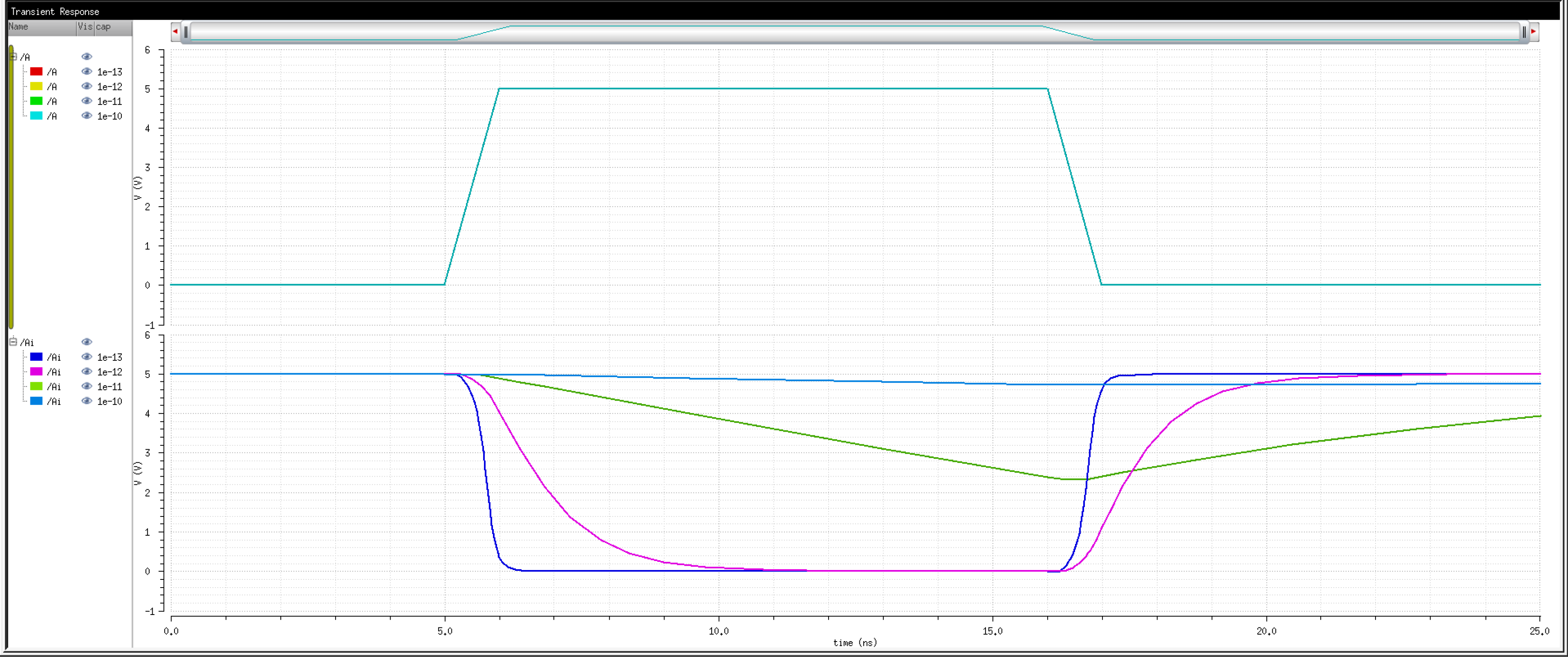
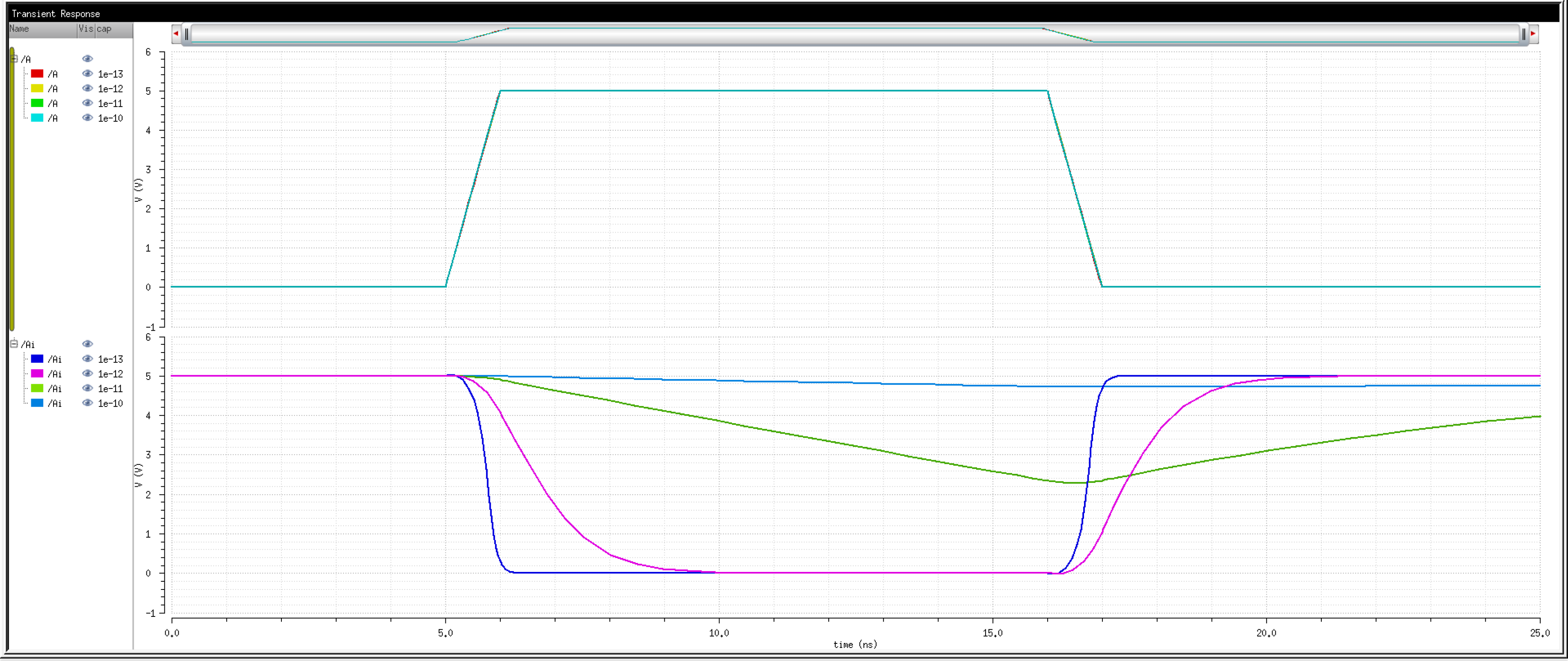
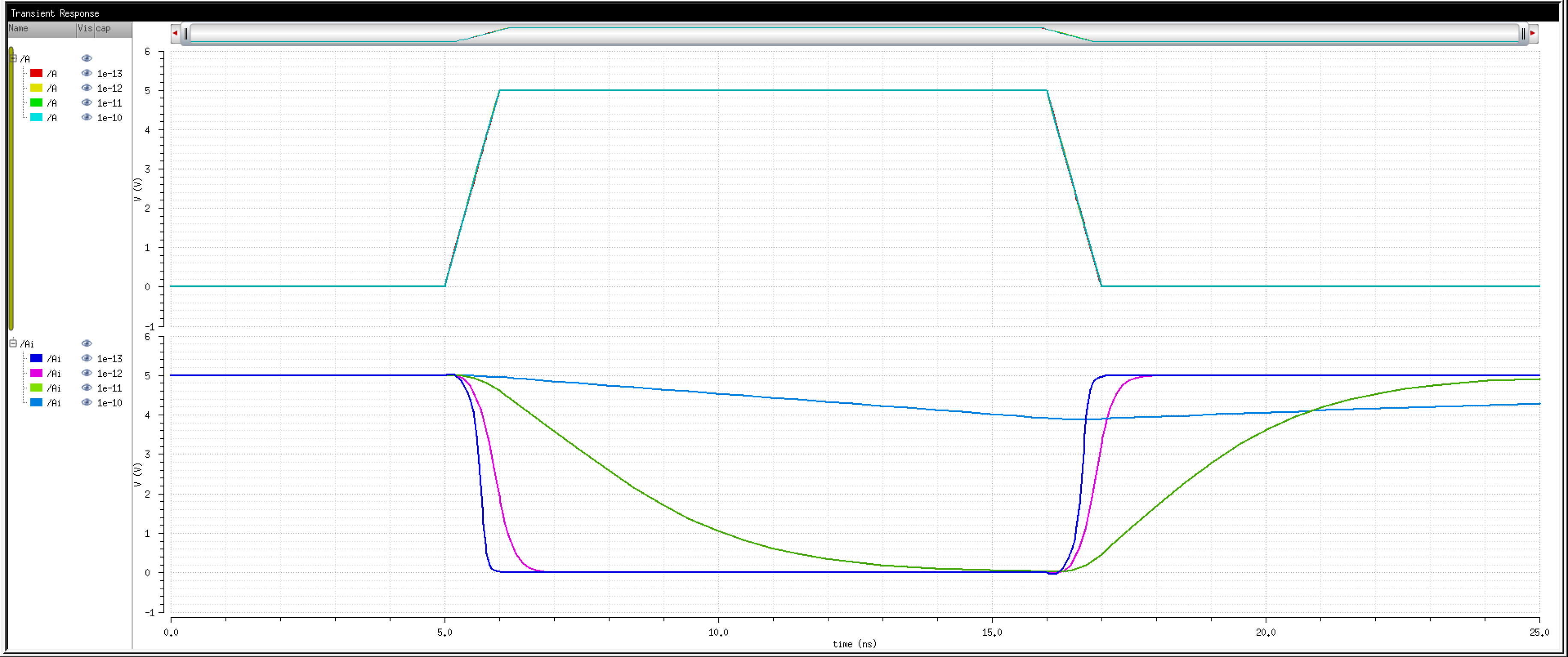
The
top waveform is the input. Digitally, it goes from 0 to 1 and then back
down to 0. We expect the output to be inverted, that is, to go from 1
to 0 and then back up to 1.
When
the capacitor has a small value, this is almost the case (notice it is
not perfect). As the capacitance increases, so does the delay. When the
time constant is large enough, there is almost no change in the output
as the capacitor has sufficient charge to keep the output where it was
originally.
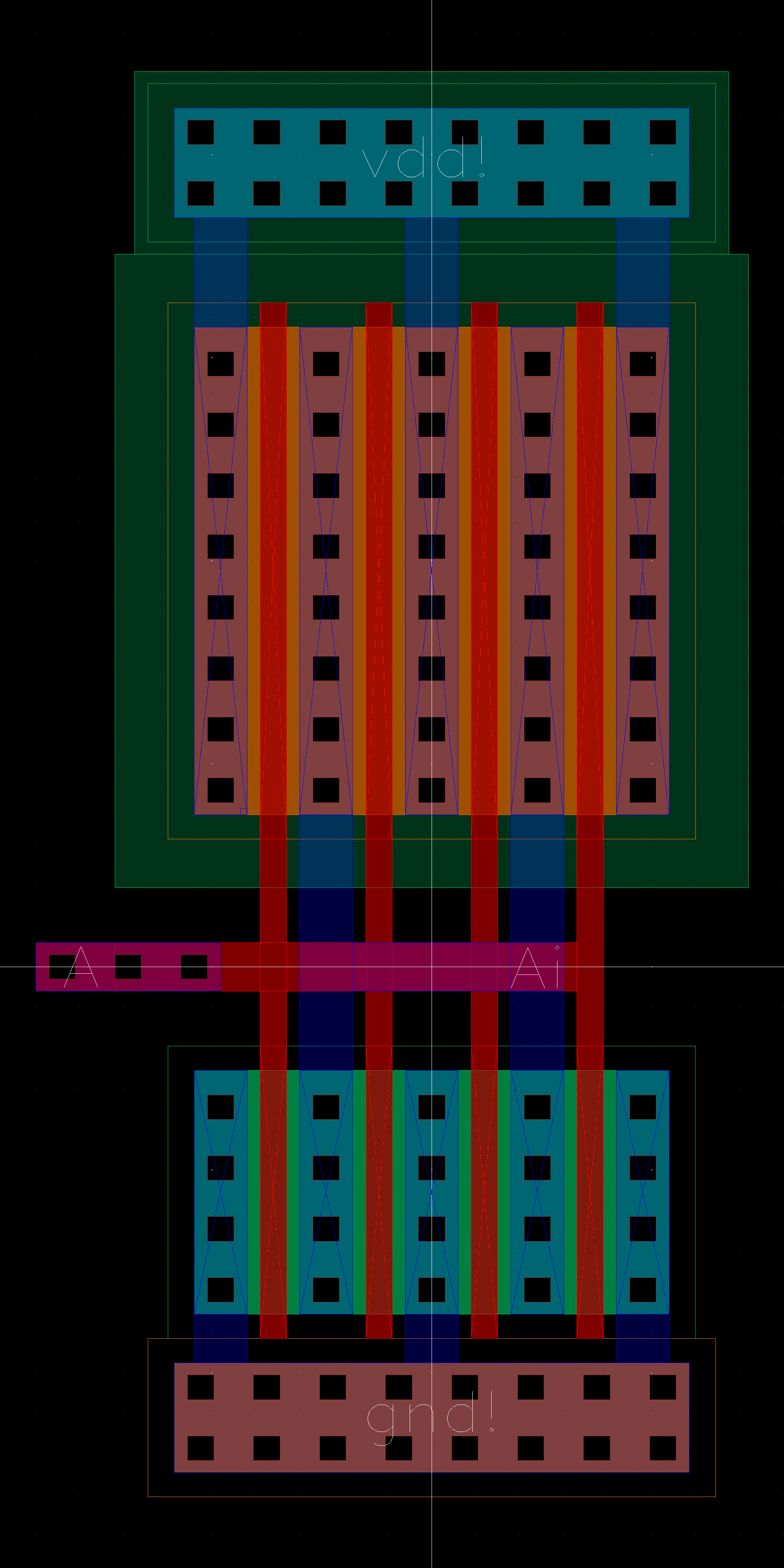
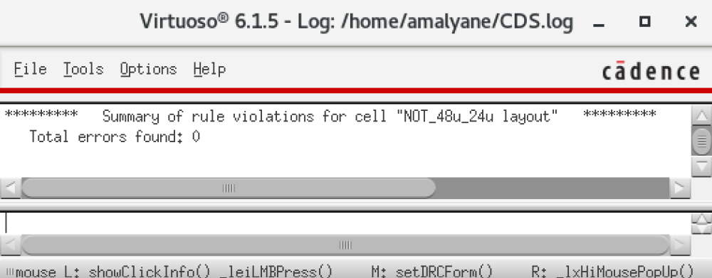
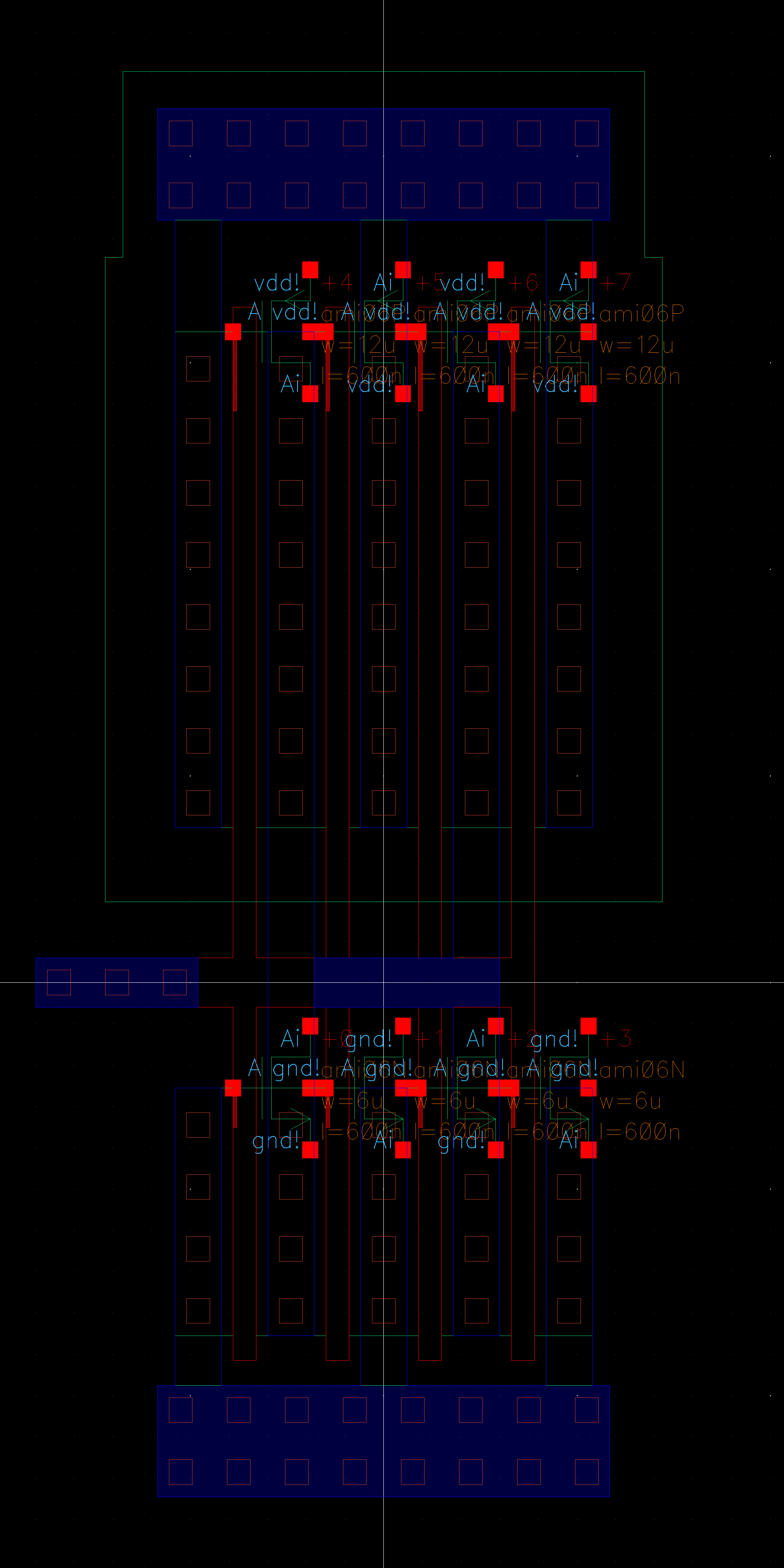
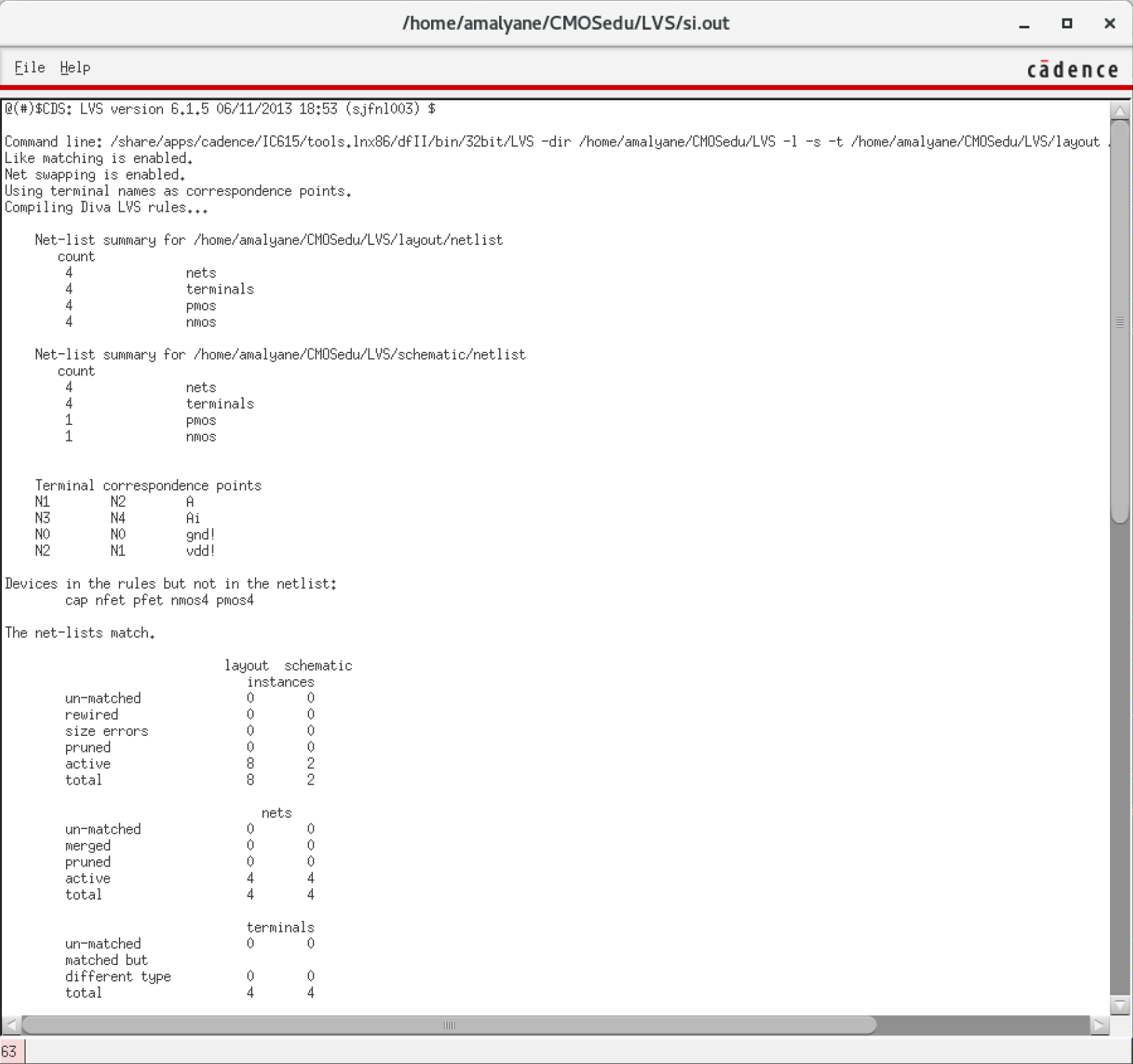
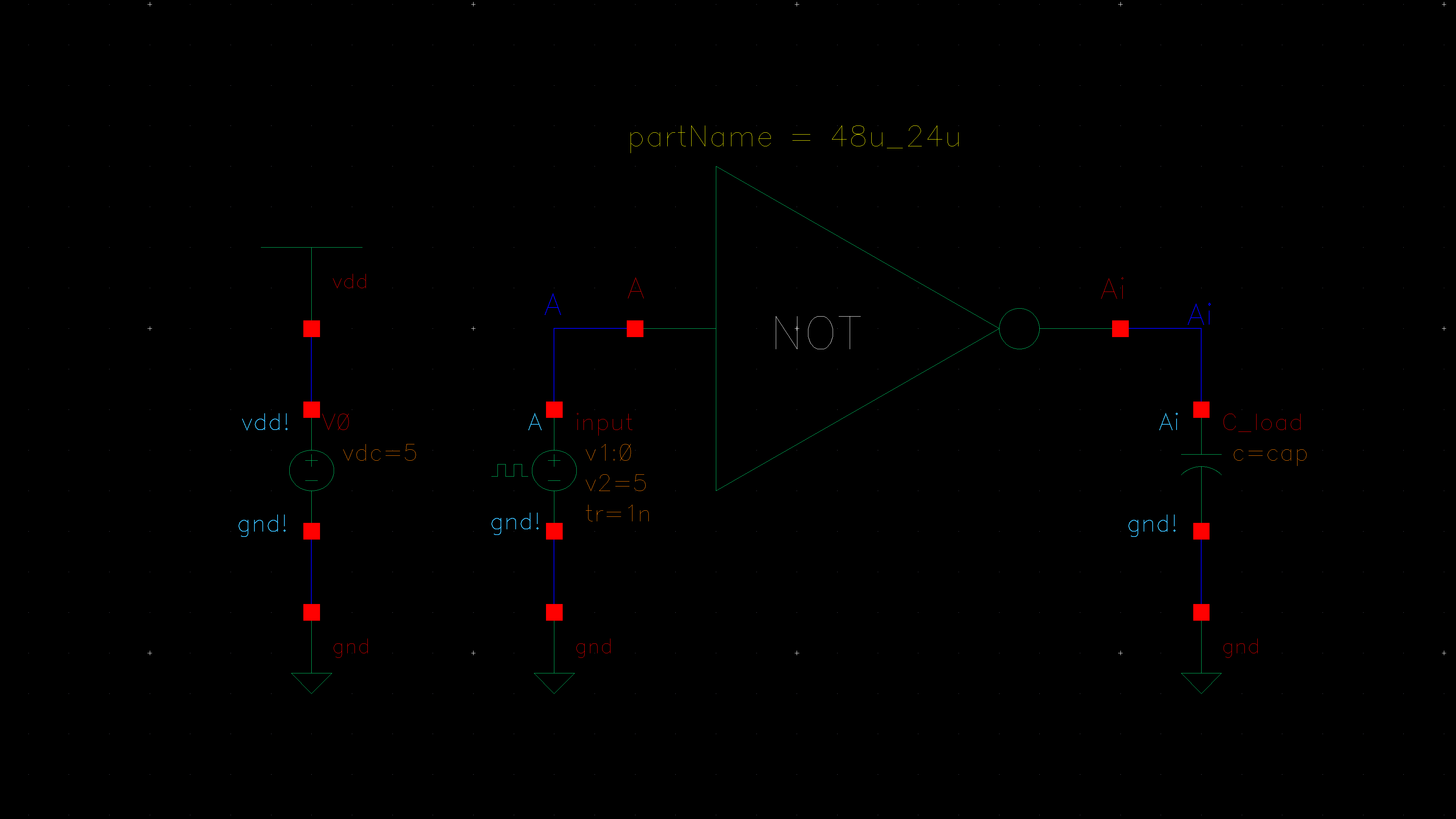
Inverter - 48u/24u
Now let's design a 48u/24u inverter. We repeat the above process with the relative adjustments.
Schematic.
Symbol.
Layout.
DRC.
Extract.
LVS.
Simulation Schematic.
Spectre:
UltraSim:
The
4 finger inverter has more area, allowing more current to flow through
to the capacitor. It seems that the delay was not solely due to the
time constant of the capacitor, but also the surrounding circuitry.
In
the past we have always simulated and characterized curcuits using
ideal components. Now we can clearly see the limitations of real world
devices.
The design files used for this lab are provided here: lab5_ea.zip
Backups:
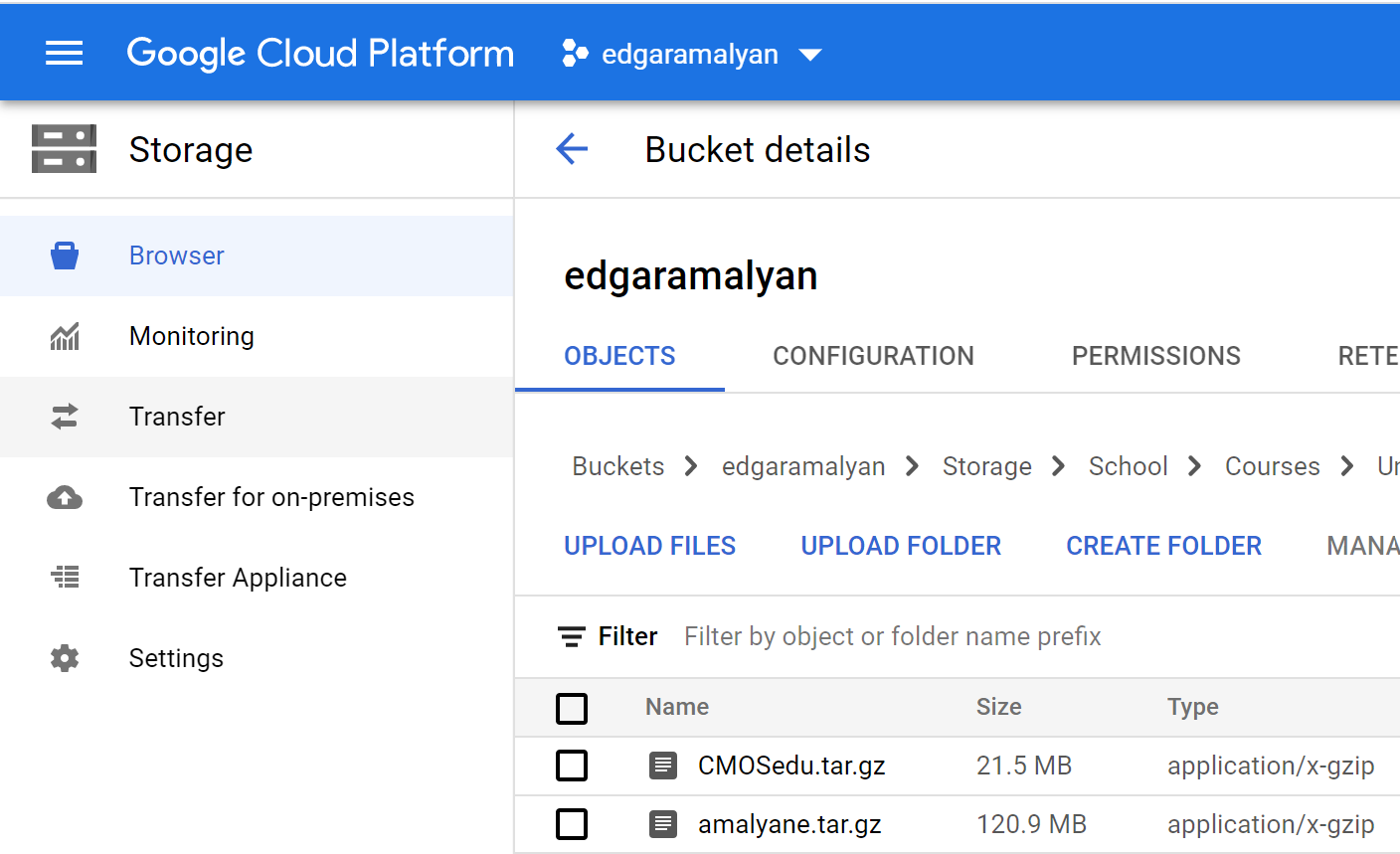
As
demonstrated in Lab 1, I run ./backup.sh from the Cadence server and
download the 'Backup' folder containing the compressed archives of my
CMOSedu and entire home directories.
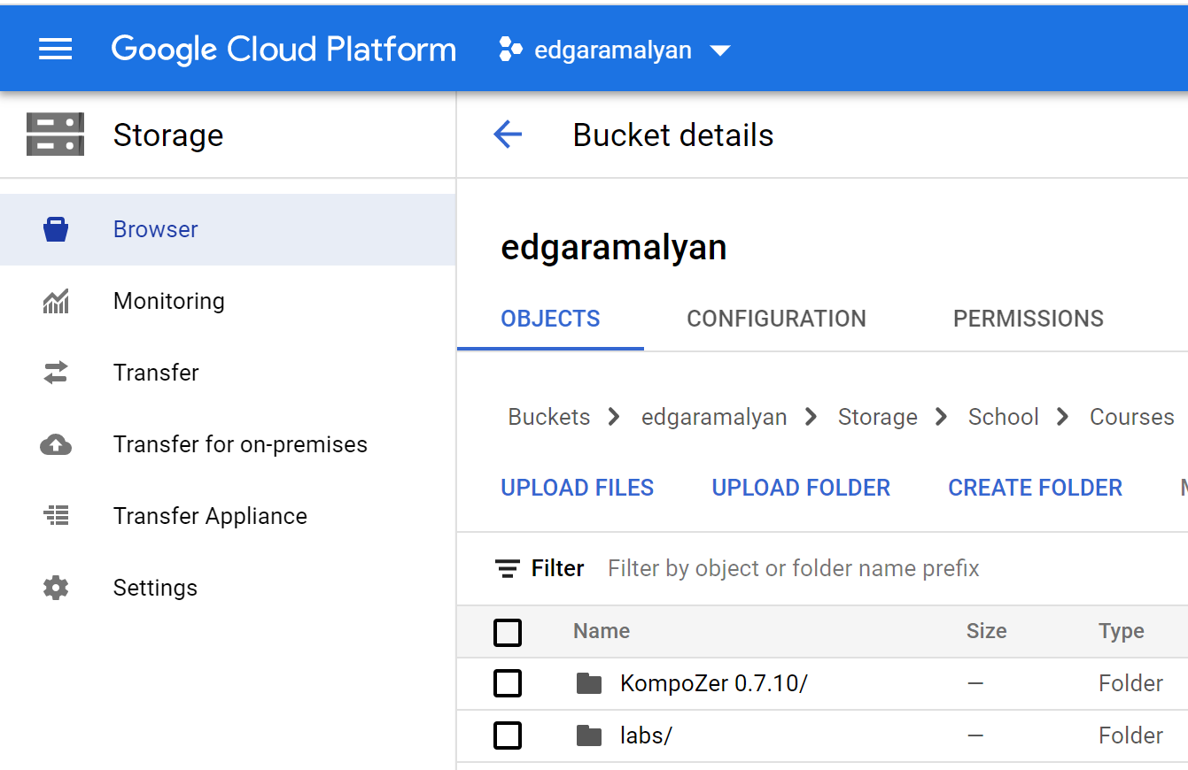
All files pertaining to this lab report already exist and are directly edited from another folder that also gets synced.
I run sync_to_gcp.bat from my computer which makes my GCP Storage bucket identical to my local directory.
Return to EE 421L Labs