EE 421L – Digital IC Design Lab – Lab 3
Layout of a 10-bit
digital-to-analog converter (DAC)
Author: Darryl Derico
E-Mail:
derico@unlv.nevada.edu
9/11/2019
Lab Description:
For this lab, I must make the
layout of the 10-bit DAC I designed and simulated in Lab 2.
The 10k ohm resistor layout needs
to be made prior to making the DAC.
Prelab:
Finished and utilized
concepts from Tutorial 1 in recent assignments.
Lab:
Link: lab3.zip
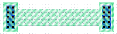
Layout of 10k Resistor for
DAC:
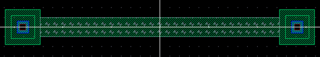
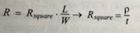
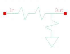
Using the above equation, I know
that R must equal 10k as I have to make the resistor 10k ohms. The sheet resistance
is between 820 and 855. Selecting 855 as the sheet resistance, I plugged 10k
into R, 855 into rho/t and calculated for the ratio of L/W, getting 11.69:1 as
a result. For the sake of ensuring the resistor doesn’t turn out too small, I
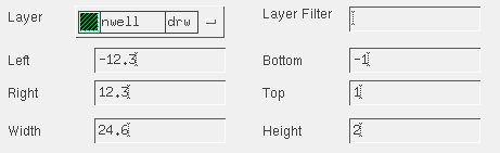
doubled the length and width using 23.4 as the length, and 2 as the width. However,
this yielded less than 10k ohms when I performed the extract. After asking Dr.
Baker for some assistance, he said to increase the length to 24.6 (or a ratio
of 12.3:1). This left me with a resistor 10.07k.
Extract of above Resistor:
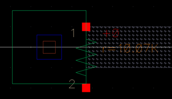
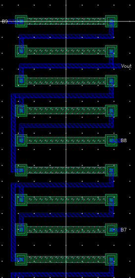
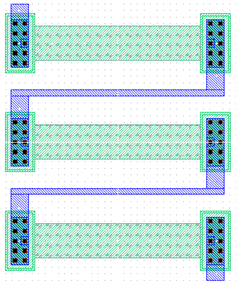
Layout of DAC using R=10k:
The layout required a total
of 28 10k resistors.
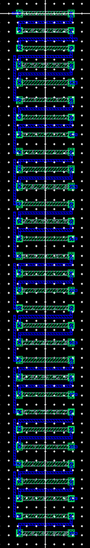
Zoomed
in: