Lab 2 - ECE 421L
Authored
by Isaac Robinson,
robins82@unlv.nevada.edu
September 14th, 2016
The focus of lab 2 is the design of a 10-bit digital-to-analog converter (DAC).
PRELAB:
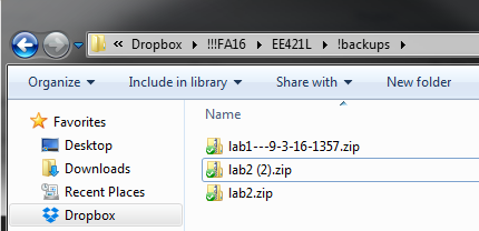
Image 1: the unziping of the lab2.zip file to the CMOSedu folder.
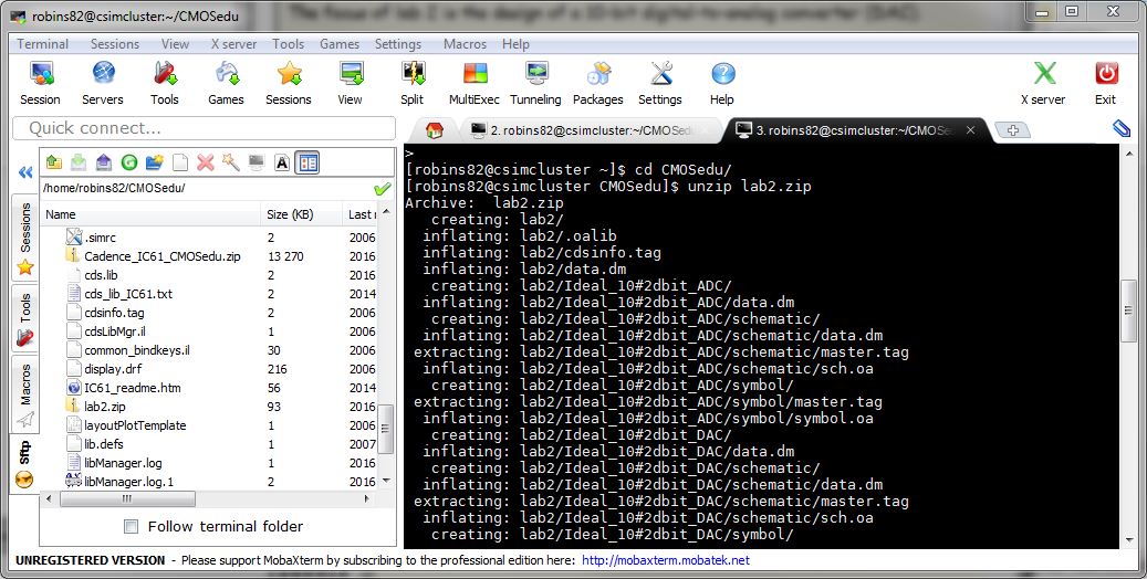
Image 2: Defining lab2 project in cds.lib
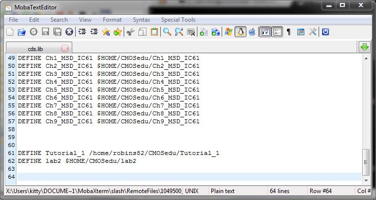
Image 3: Selecting the sim_Ideal_ADC_DAC schematic from the lab2 project
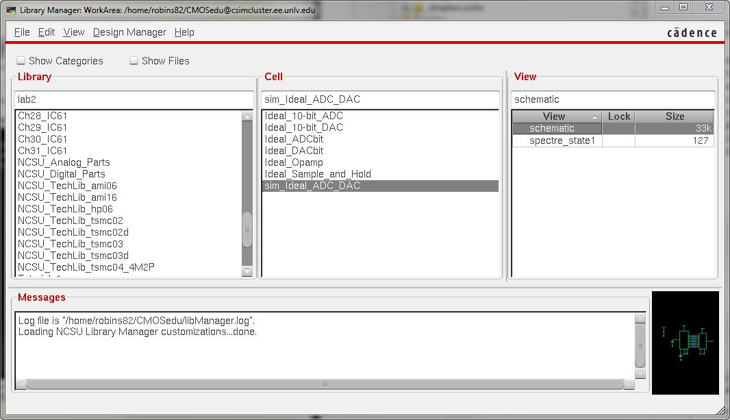
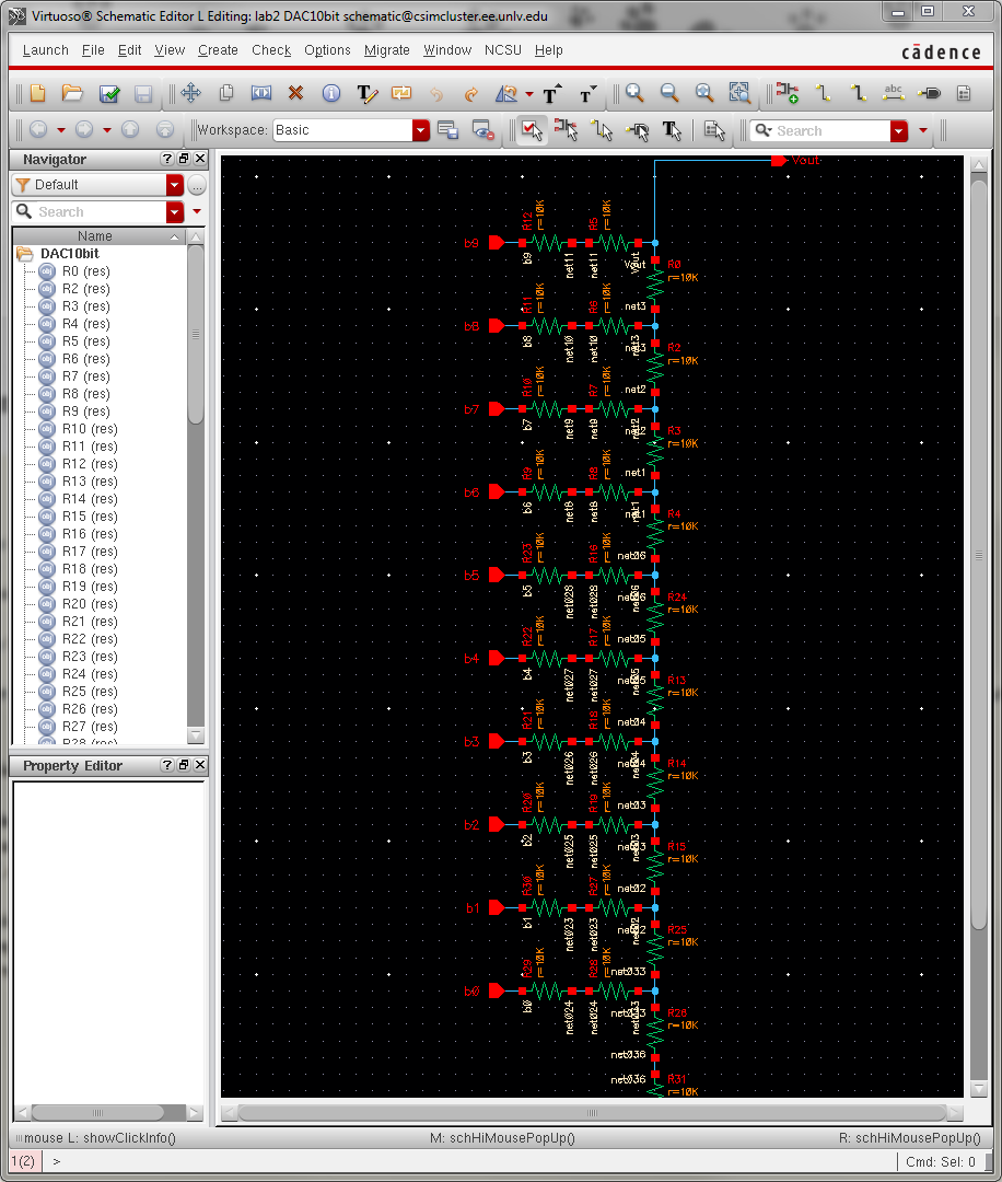
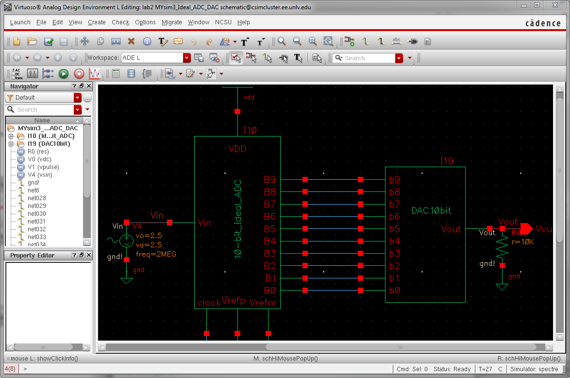
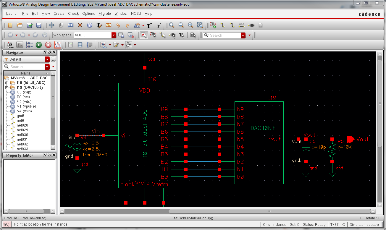
Image 4: The sim_Ideal_ADC_DAC schematic
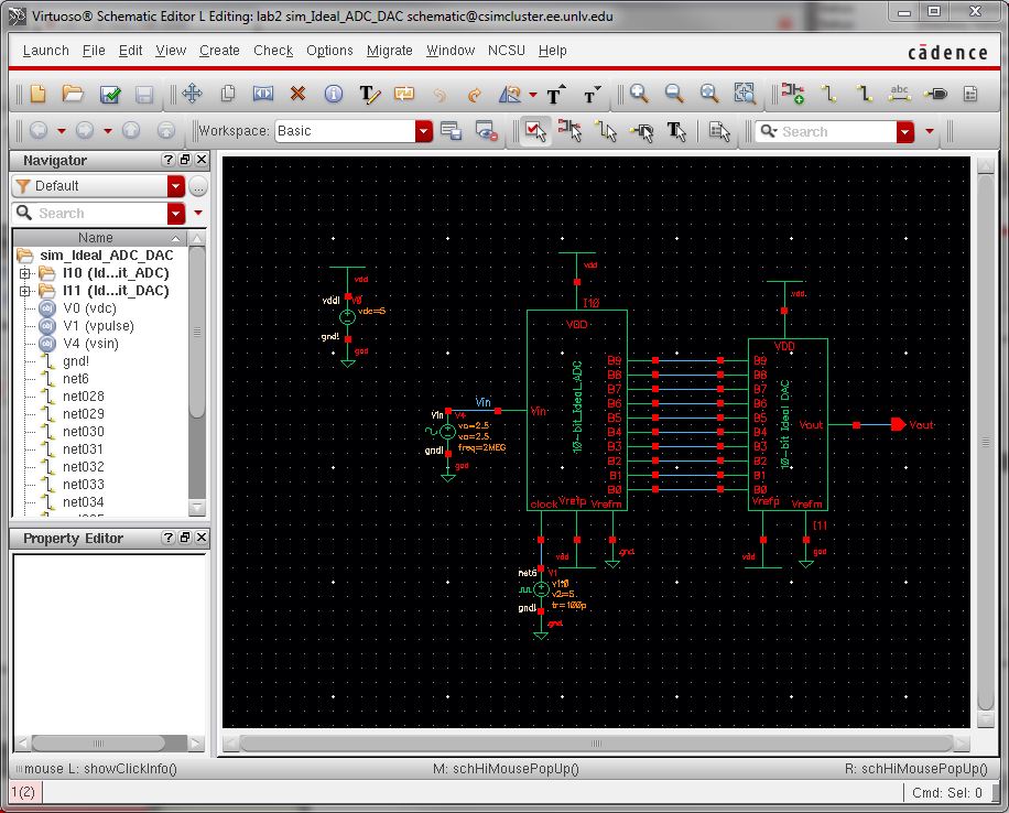
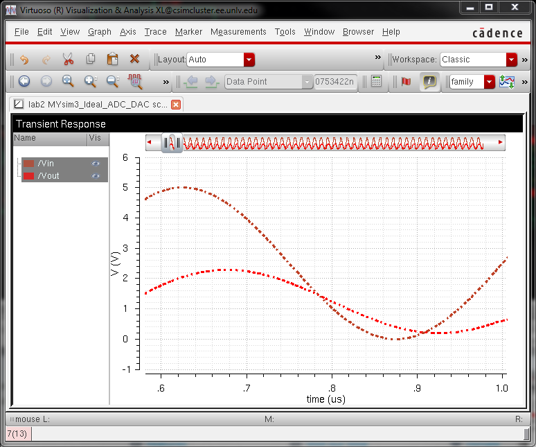
Image 5: The simulator of this circuit for 1uS.
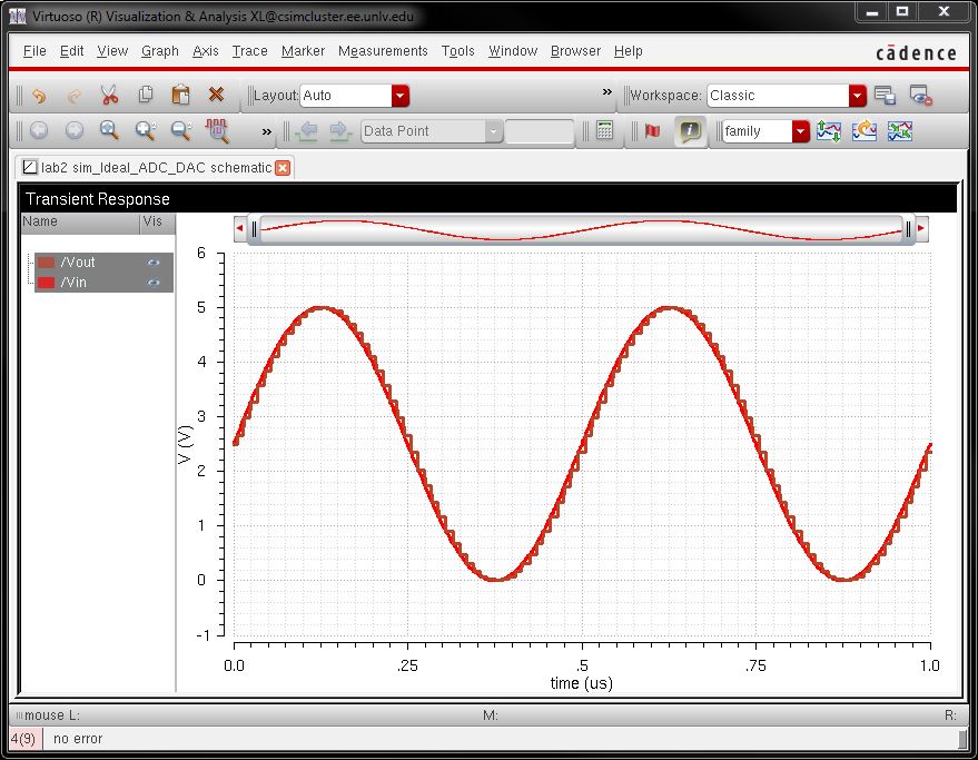
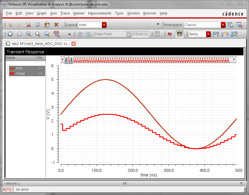
Image 6: Changing the input Amplitude from 2.5V to 5V
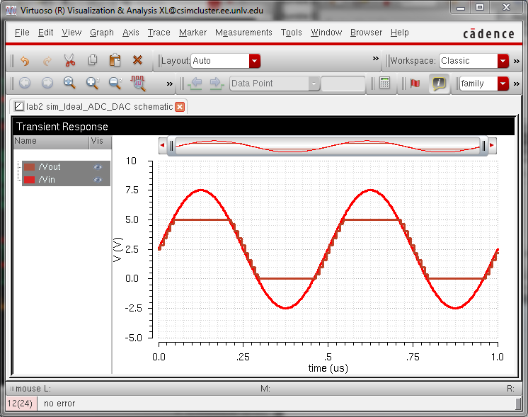
What can be observed here is that data is being lost when input voltage is greater than 5V or a negative value.
The DAC will output 5V when the input voltage of the circuit is above 5V and will display 0V when below 0V.
--------------------------------------------------------------------------
--------------------------------------------------------------------------
LAB REPORT:
The design of a 10-bit DAC using an n-well R of 10k:
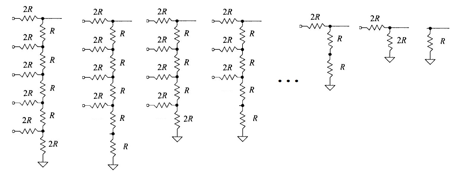
How to determine the output resistance of the DAC:
By continually combining the two bottom most resistors, we end up with the resistance of 1R. This process is shown below.
Delay, driving a load:
Grounding pins b0 to b8 and sending a step voltage to b9, with a 10pF load:
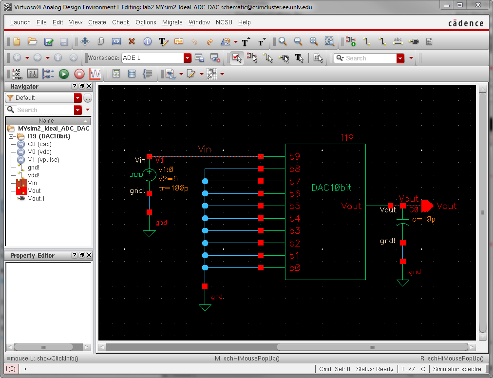
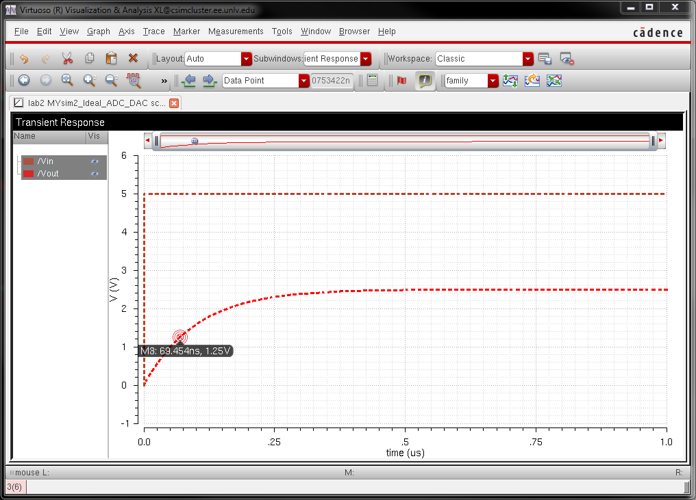
delay time = 0.7RC = 0.7 * 10k * 10pF = 70ns
At this point the voltage should be half the final output voltage (2.5V / 2 = 1.25V).
The hand calculations match the graph plotted by Cadence.
DAC driving 10k load:
Because
the resistance of the DAC is R, and we place a R in series with the
DAC, this acts like a voltage divider, cutting the output voltage in
half.
DAC driving both load and resistance:
As we can see, since the load use was R, the output is still cut in half and there is a phase shift due to the capacitor.
In a real circuit the switches seen above (the outputs of the ADC) are
implemented with transistors (MOSFETs). - Discuss what
happens if the resistance of the switches isn't small compared to R.
This
system relies on uniform resistances to have uniform DAC outputs, in
other words the output scaling of the DAC would be affected.
BACKUPS:
Return to Isaac's Labs
Return to EE 421L Labs