Lab Project - ECE 421L
Michael Villalba,
11-10-2014
For
the project we will be building an 8-bit ALU, which will include the
following operations: ADDITION, OR,and SUBTRACTION, and AND gate.
For the first half of the project we will construct the schematic and symbol for the 8-bit ALU.
First thing to do is to build the 1-bit ALU schematic.
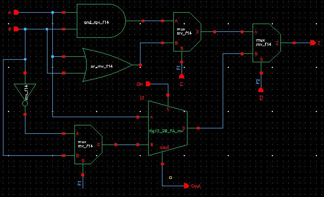
Using
the MUX's from lab 7 allows us to select the operation function
when S=1 it pulls A and S=0 it pulls B, giving us the functions (addition: F1=0 F2=0, or:F1=0
F2=1, subtraction: F1=1 F2=0, and:F1=1 F2=1). We are using 2's compliment for subtraction we we will look at the
greatest extra bit (Cout).
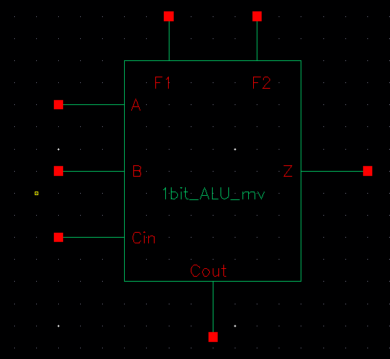
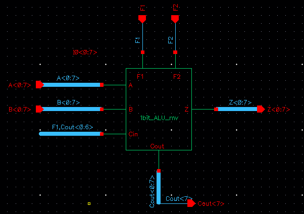
Here is the symbol for the 1-bit ALU
Simulation of the 1-bit ALU: Testing all combinations of A and B.
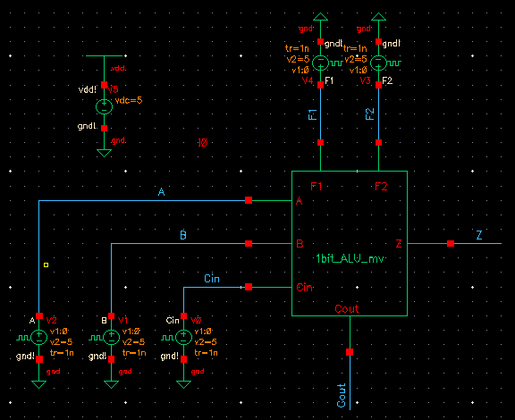
For all operations except ADD we ignore cout and we ignore cin=1 except subtraction.
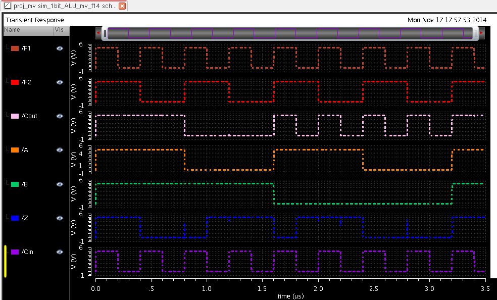
Ex1: A=1 B=1
Add: F1=0, F2=0 we see Cout=1 and Z=0 (1+1=10).
Or: F1=0, F2=1 we get Z=1 while ignoring cin and cout.
Subtraction:
F1=1, F2=0 we get Cin is the same as F1 so Cin=1, then we get Cout=1
and Z=0 (1-1=00), Cout=1 which is the extra bit. (from 2's compliment).
And: F1=1, F2=1 we get Z=0 ignoring cin and cout.
Ex2: A=0 B=1
Add: F1=0, F2=0 we get Z=1 and Cout=0
Or: F1=0, F2=1 we get Z=1 while ignoring cin and cout.
Subtraction: F1=1, F2=0 we get Cin is the same as F1 so Cin=1, then we
get Cout=0 and Z=1 (from 2's
compliment).
And: F1=1, F2=1 we get Z=0 ignoring cin and cout.
After every combination it appears that our ALU is working.
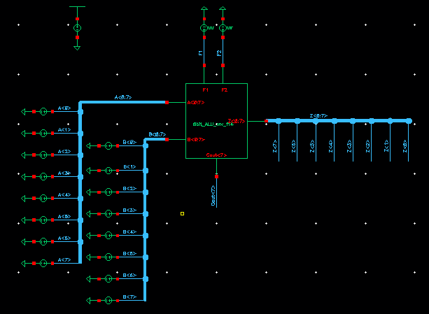
Now we have to convert the 1-bit ALU to an 8-bit ALU using the methods from lab 7:
Now we have to simulate the 8-bit ALU:
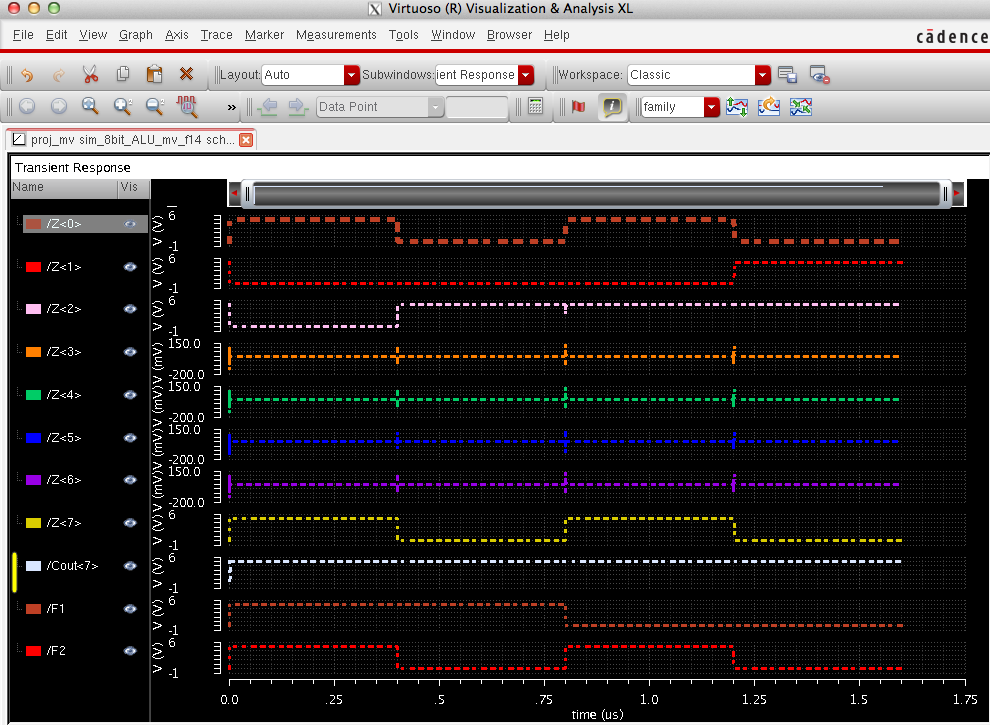
when A=10000101 and B=10000001
Add: F1=0 F2=0, Z=000100110, cout=1 which makes it 9 bits (correct)
Or: F1=0 F2=1 is Z=10000101
subtraction:F1=1 F2=0 Z=00000100
And: F1=1 F2=1 Z=10000001
which is correct.
Since the 8-bit ALU is working this concludes the first portion of the project.
PART 2 OF LAB:
For
this portion of the lab we will be constructing the layout of the of
the 1bit-ALU which will then lead to creating the layout for the
8bit-ALU.
Here is the layout of the 1bit-ALU:
Now here is the LVS of the layout to make sure it is working:
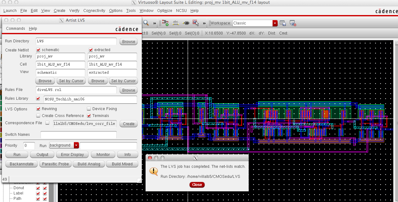
Just to be sure we have to check the output file of the LVS:
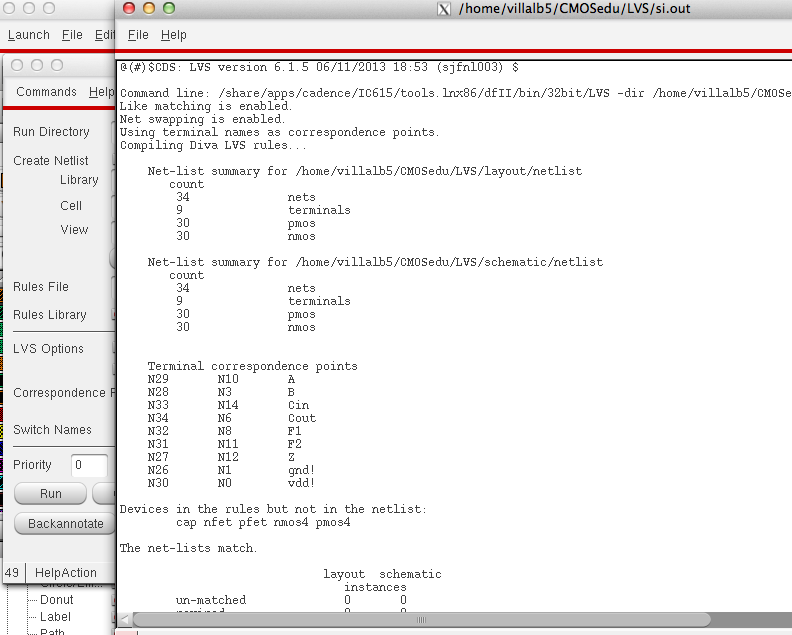
AND IT IS A MATCH. Now we can proceed to the 8bit-ALU.
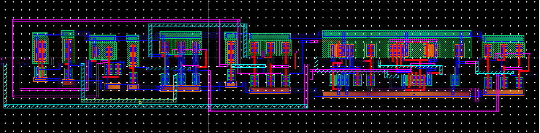
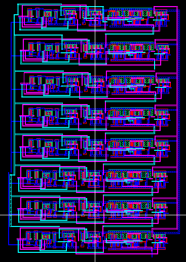
Here is the layout of the 8bit-ALU:
Now to LVS the 8bit-ALU:
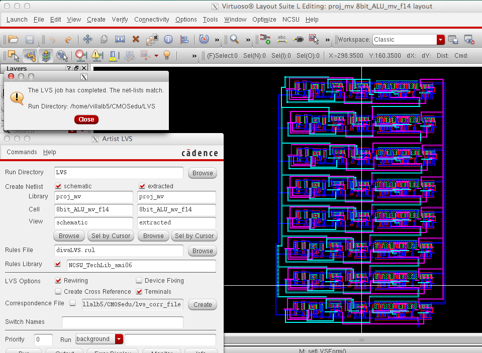
Again we need to be sure that it is a net-list match so we have to take a look at the output file
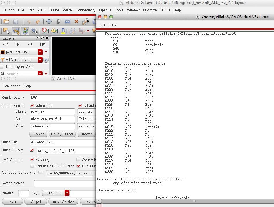
YAAAAYYYY!!!! IT IS A MATCH. =)
This now concludes the project for the lab.
My file for the lab can be downloaded here: proj_mv
Here is me backing up my work.
Return to Michael's labs