Lab Project - ECE 421L
Design, layout, and simulate an 8-bit ALU that can perform A+B, A-B, A AND B, and A OR B.
In this project we will use the logic gates created in lab 7. Using these gates we will create a 1-bit ALU and then we will cascade 8 1-bit ALUs to create our 8-bit ALU.
The 1-bit ALU has four inputs and two outputs. The inputs are A, B, F1 and F0. The outputs are Z and Cout.
The ALU will perform the following operations depending on the operation selectors, F1 and F0.
| F1 | F0 | Operation |
| 0 | 0 | A+B |
| 0 | 1 | A-B |
| 1 | 0 | A OR B |
| 1 | 1 | A AND B |
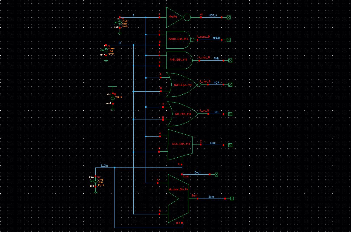
| Gates Simulation Schematic |
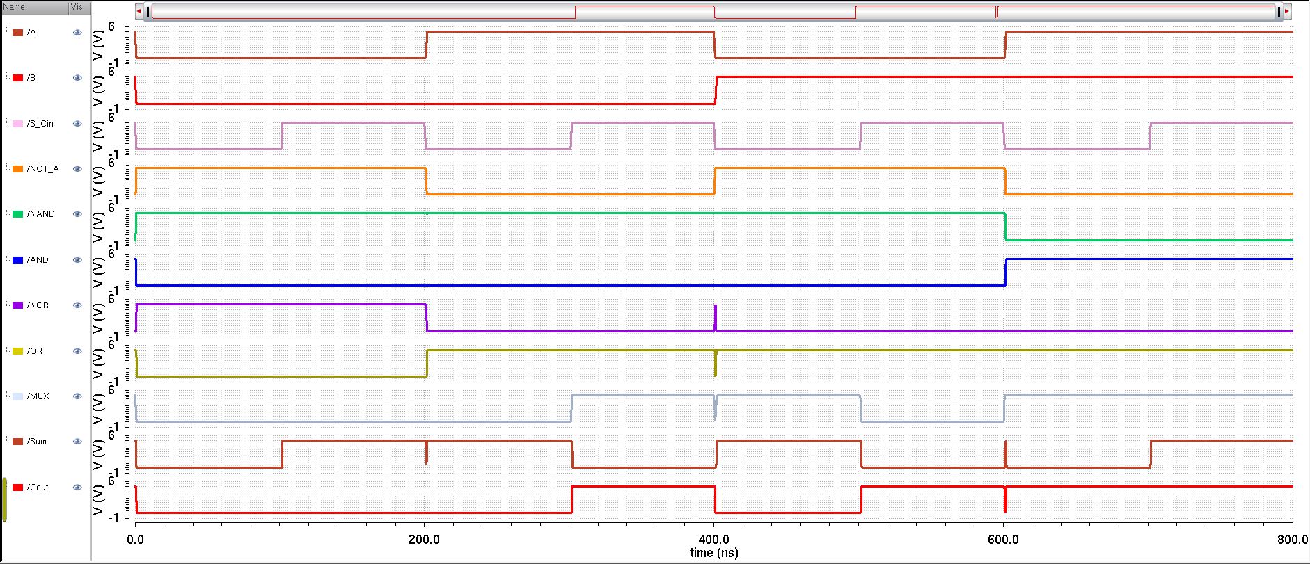
| Gates Simulation Results |
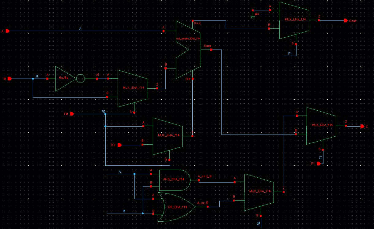
Then we create a symbol for the 1-bit ALU and also proceed to simulate it to check the operations are done correctly.
Symbol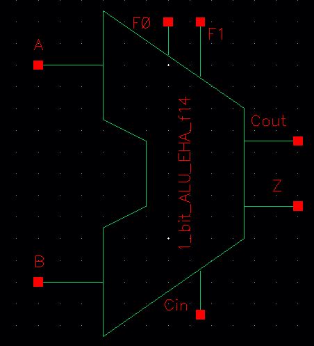 | Simulation Schematic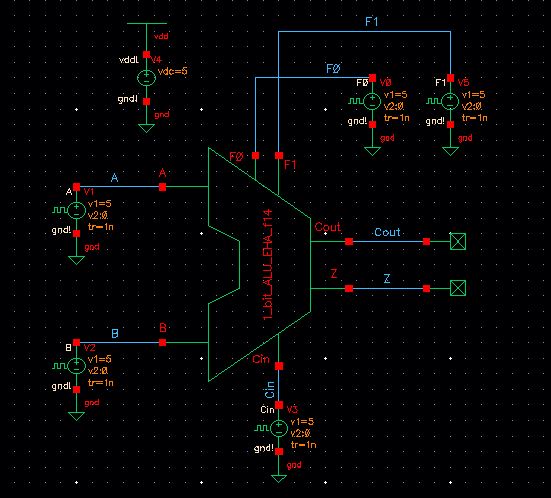 |
Simulation Results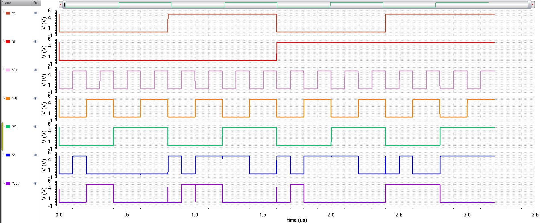 | |
As it seen in our 1-bit ALU simulation, it operates correctly. Now we proceed to create an 8-bit ALU by cascading 8 1-bit ALUs.
8-bit ALU schematic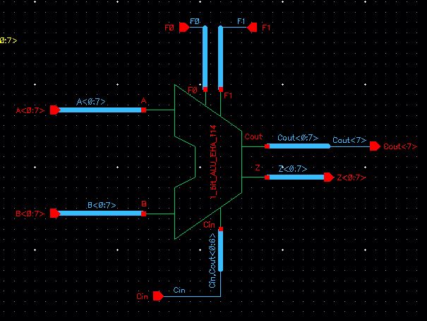 | 8-bit ALU symbol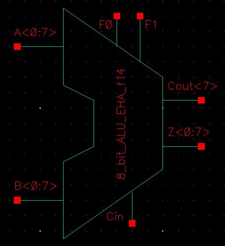 |
8-bit ALU simulation schematic. We will let A equal 11101010 (234) and B equal 10111010 (186).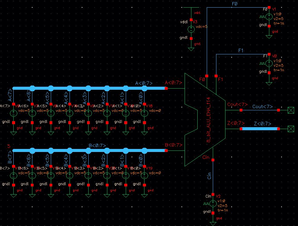 | |
| 8-bit ALU simulation results. The following results are observed A+B= (420) 110100100 A-B= (48) 110000 A OR B= 11111010 A AND B= 10101010 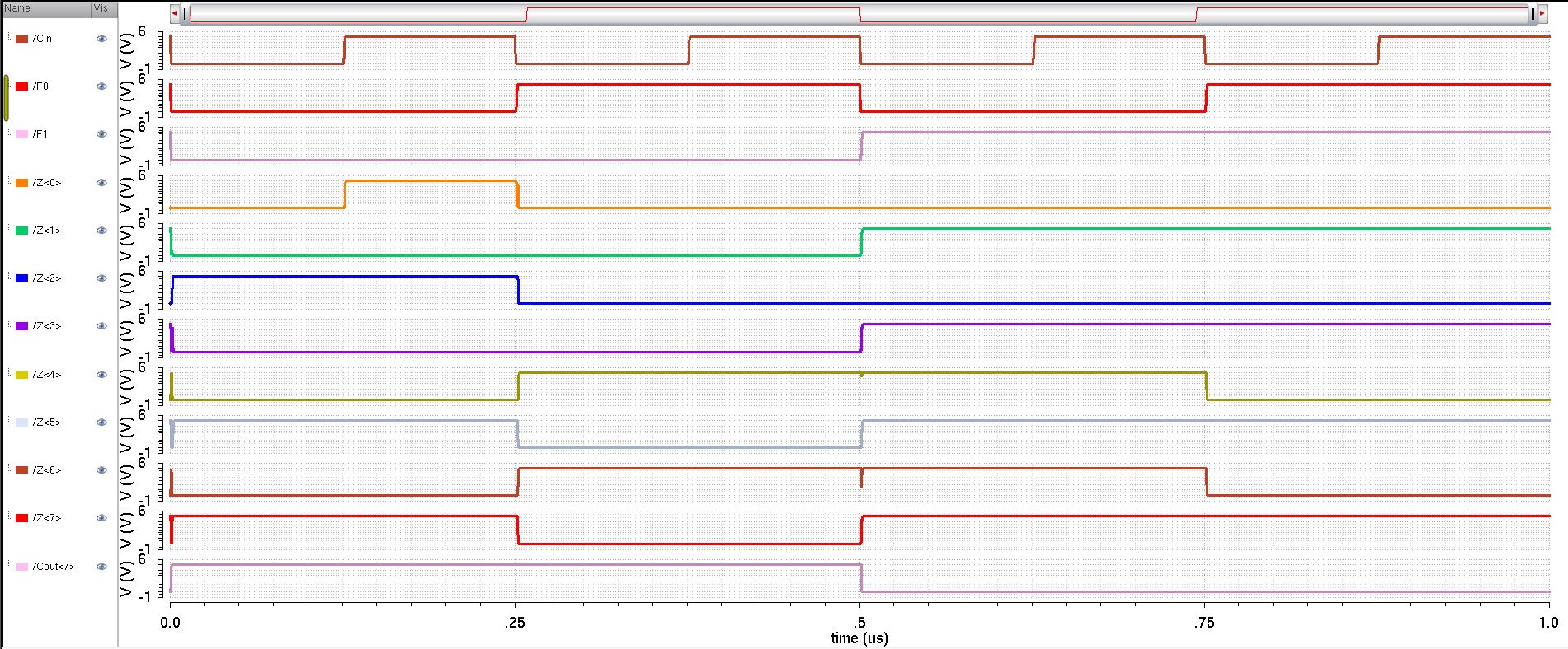 | |
8-bit ALU simulation schematic. We will let A equal 11100000 (224) and B equal 10000111 (135).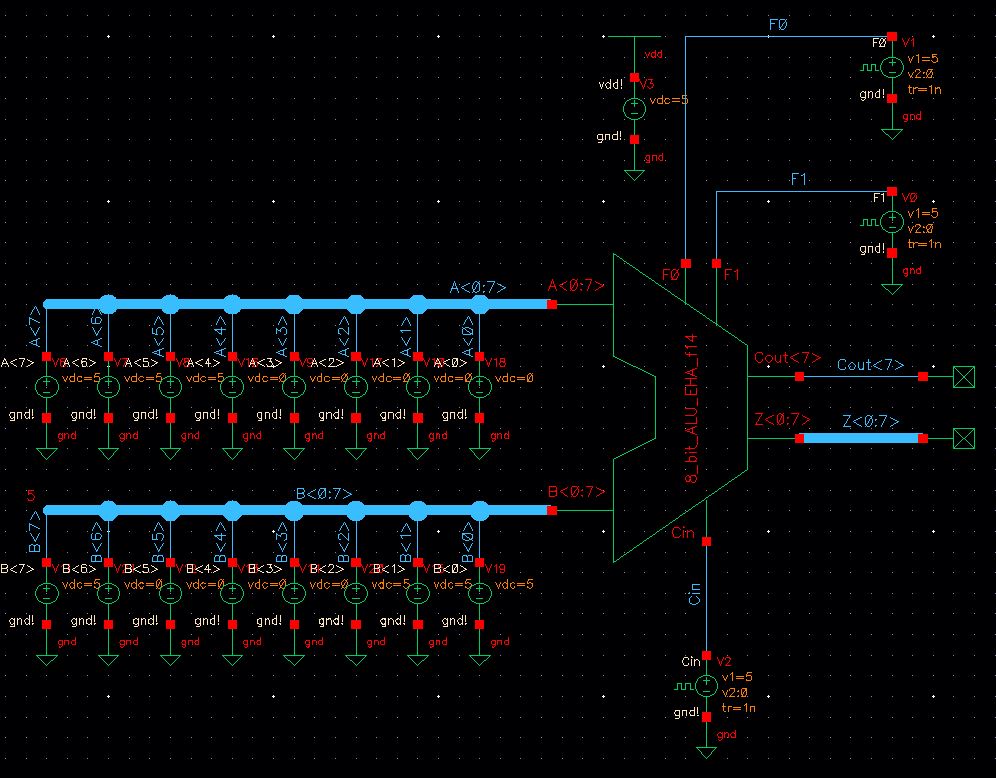 | |
| 8-bit ALU simulation results. The following results are observed A+B= (359) 101100111 A-B= (89) 1011001 A OR B= 11100111 A AND B= 10000000 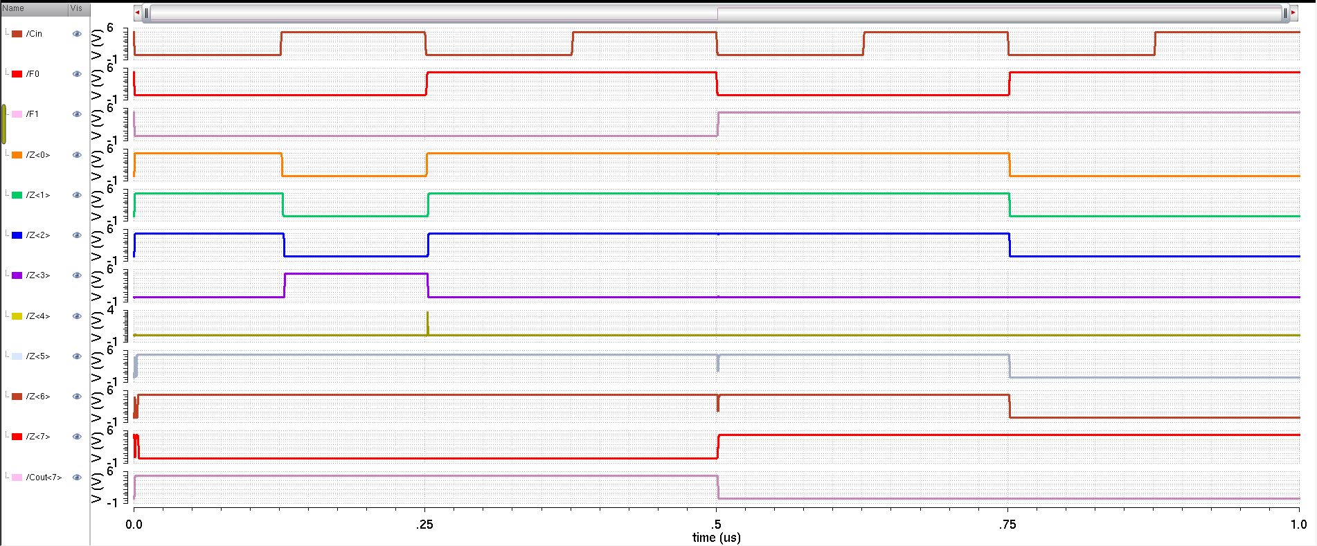 | |
Now
that we now our ALU works properly, we proceed to create the layouts
for each component used in the 1-bit ALU. We will layout a 1-bit
full-adder (lab 7), 1
inverter, 1 MUX, 1 OR gate, and 1 AND gate.
1-Bit Full Adder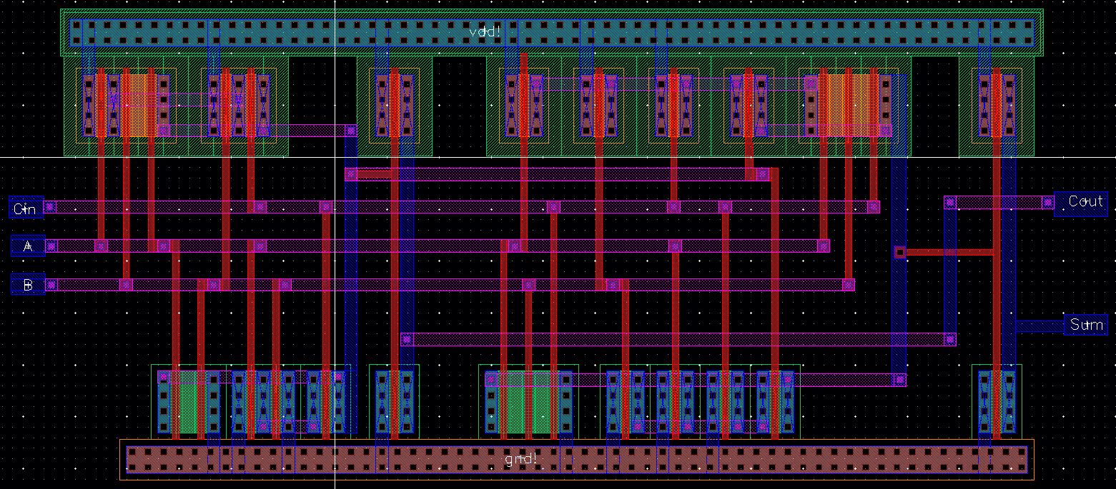 | ||
Inverter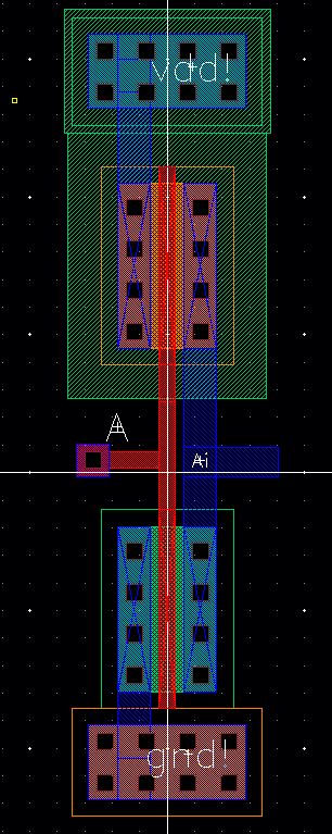 | OR Gate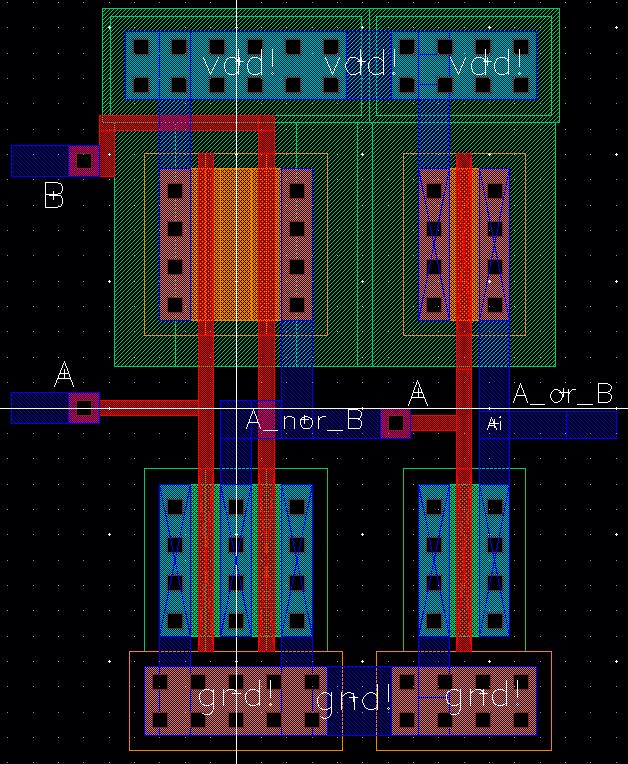 | AND gate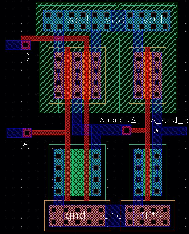 |
MUX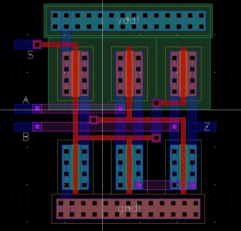 | ||
Now that we have created all the required layouts, we proceed to put them together to create the 1-bit ALU. WE will also DRC and LVS the design.
1-bit ALU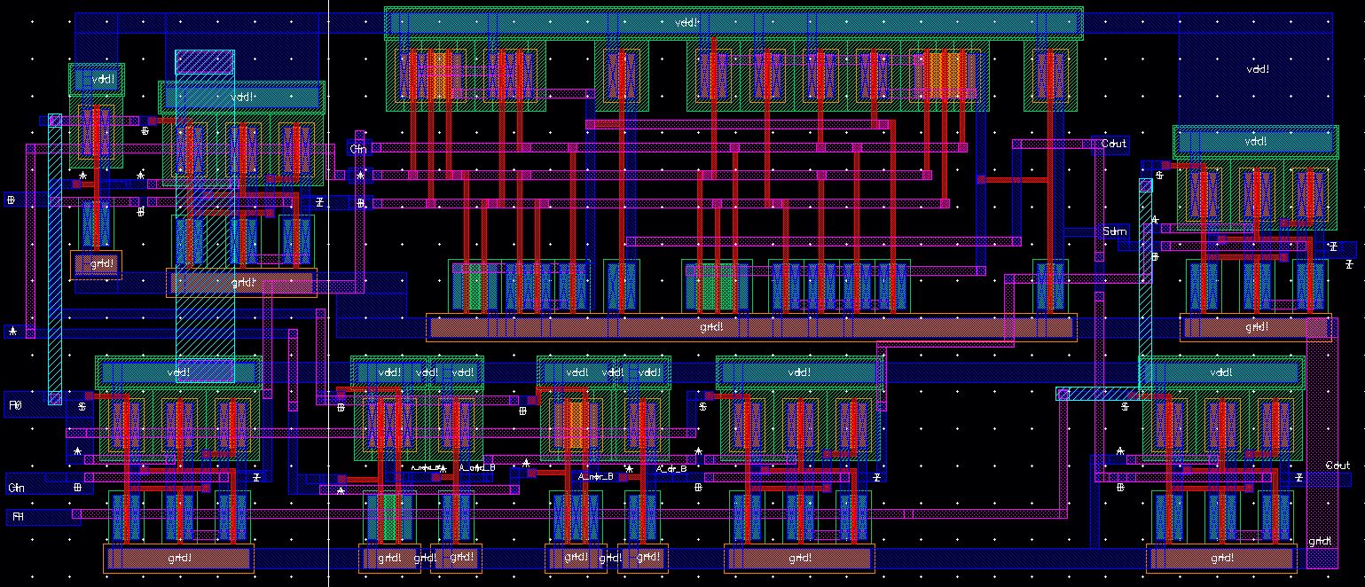 |
1-bit ALU DRC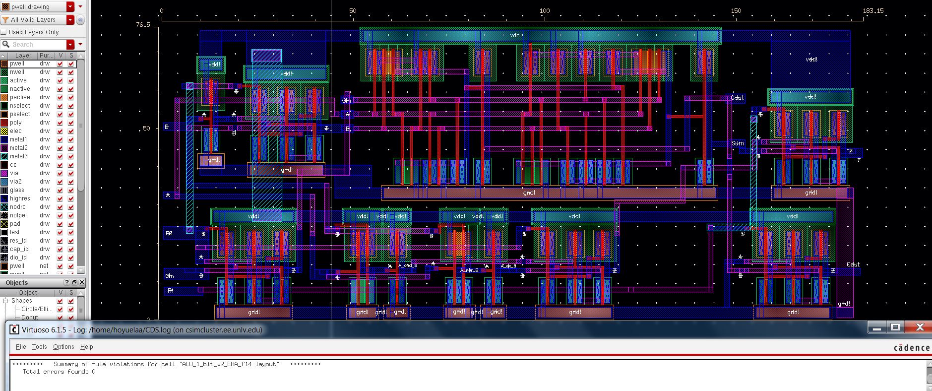 |
1-bit ALU LVS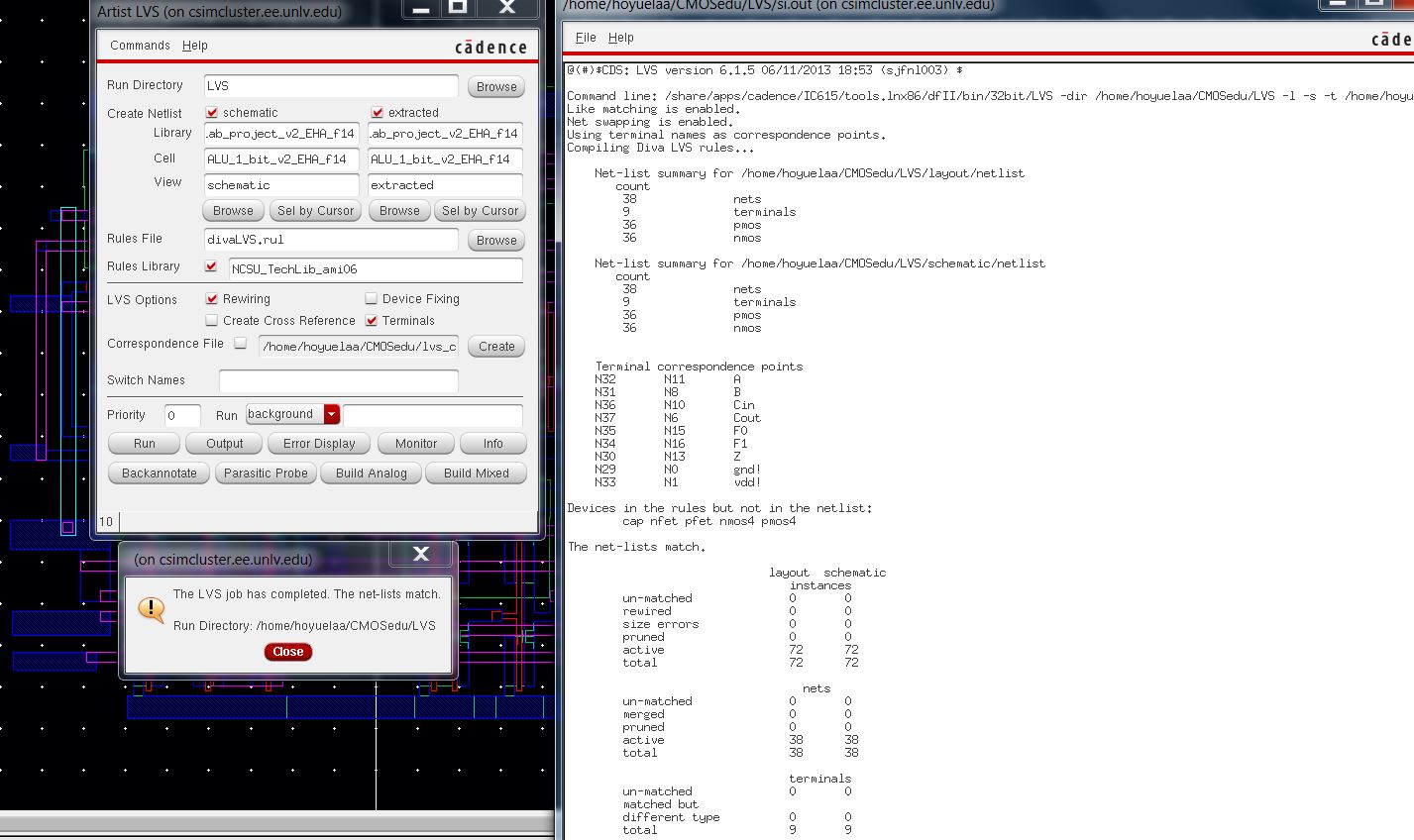 |
Now we proceed to created our 8-bit ALU by cascading 8 1-bit ALU layouts as it was done in our schematic. Again we DRC and LVS our design.
8-bit ALU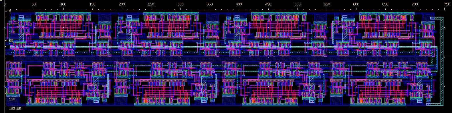 |
8-bit ALU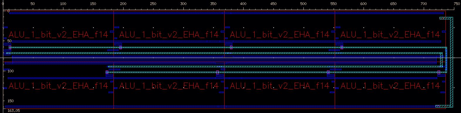 |
8-bit ALU DRC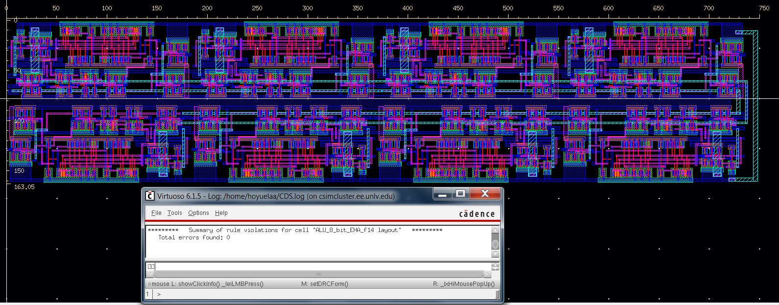 |
8-bit ALU LVS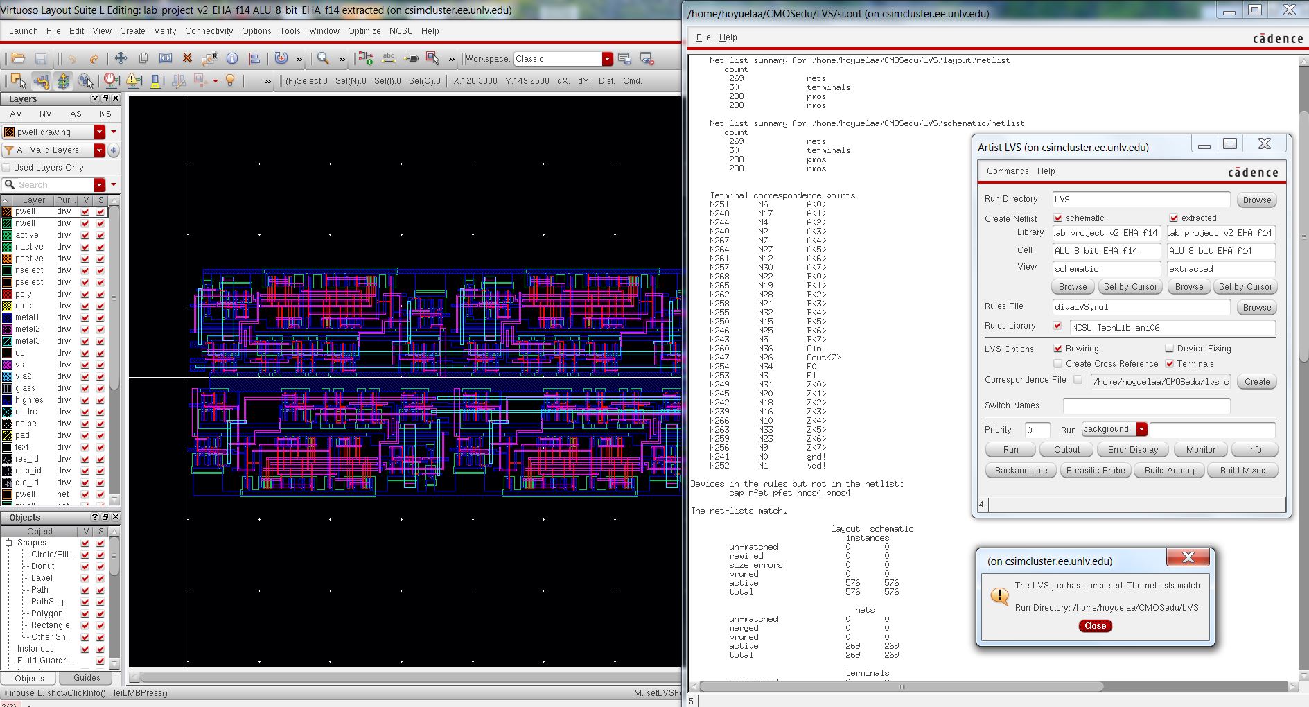 |
The design of our 8-bit ALU is done and can be placed on a chip easily as it only measures 750um x 163um. This design can still be modified so it is more compact or it takes less space if more things want to be added to the chip. I decided to cascade 8 1-bit ALUs as it seemed to be the easiest way to create the layout. Also, I could have used the 8-bit full adder from lab 7 and laid out the rest of the gates in a different configuration but it appeared to be more complicated in the layout stage.
This project is done and now we back up our files in Google Drive and on our desktop.
 |  |
Download PROJECT_ HOYUELA_EDUARDO