
Lab 1 - EE 421L
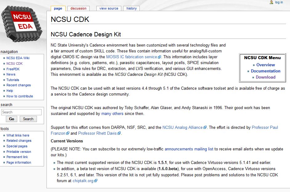
Downloading Cadence: I started by downloading the NCSU Cadence Design Kit from http://www.eda.ncsu.edu/wiki/NCSU_CDK
I unzipped the file in my home directory and added the following lines to my .bashrc file
export SPECTRE_DEFAULTS=-E
I then created a design directory called CMOSedu.
After copying everything from $HOME/ncsu-cdk-1.60.beta/cdssetup into $HOME/CMOSedu, I made cdsinit, simrc, and cdsenv hidden in the CMOSedu directory
I then updated some library definitions in my cds.lib file to include the correct paths:
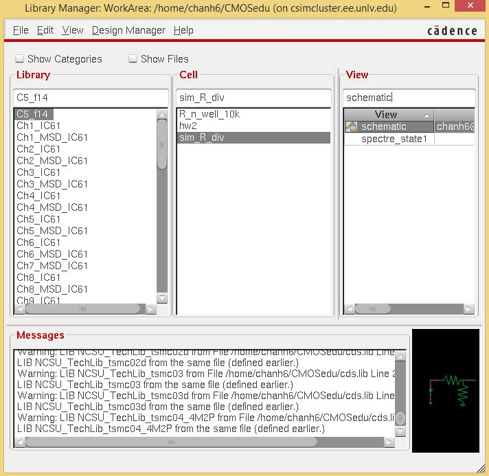
After further configuration and setup dealing with default simulator specifications and rule checking files, I remotely opened Cadence using MobaXterm.
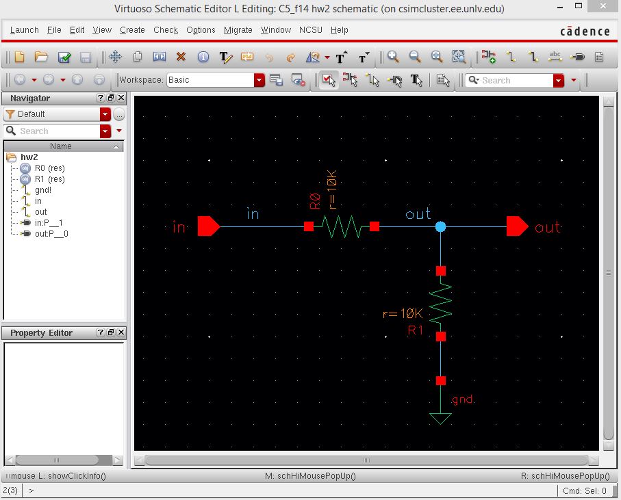
From here I created some new schematics and symbols to represent a 10k resistor divider:
10k resistive divider schematic
10k resistive divider symbol
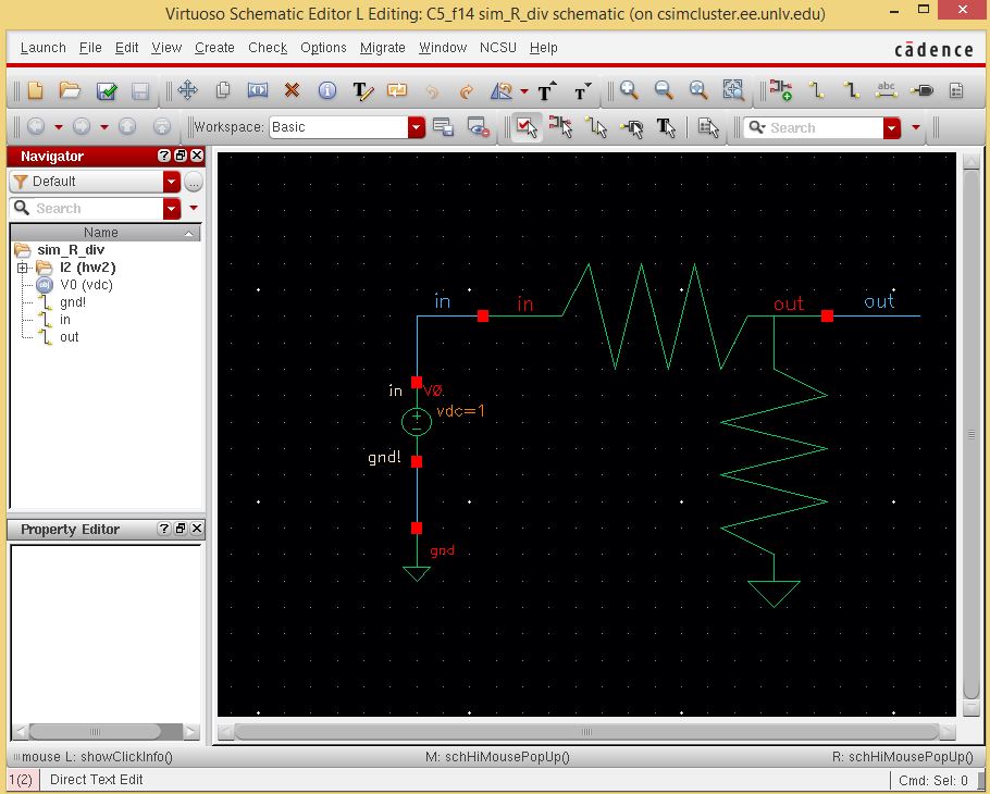
The results of the simulation appear below:
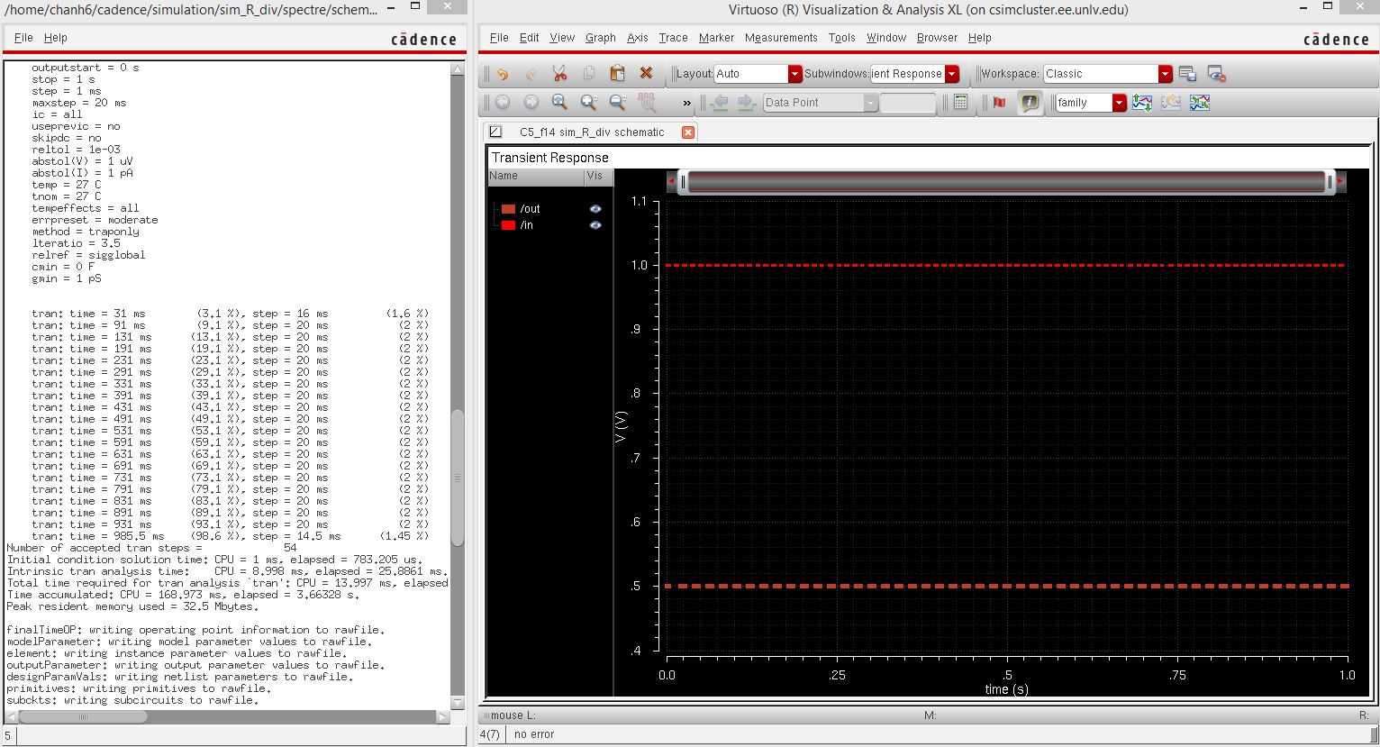
After following the tutorial, I have successfully produced a working circuit schematic and have become very familiar with the cadence tools as well as the kompozer application to complete further lab reports easily.
Backups:
For all labs, I plan on using a cloud based solution to create backups of my work. This involves saving files and images to Microsoft's Onedrive system so that I may access the material from anywhere with an internet connection.