Lab 2 – Operation of a Compensated Scope Probe
EE 420L Analog IC Design
Lab Date: 1/30/19 Due: 2/06/19
Last Edited on
2/06/19 at 1:11am using Word
When we are
testing our nice circuits for voltage outputs, we want to know what is truly
being outputted from a circuit. In the DC world, our oscilloscope will show us
what is happening on the board, however, when testing for AC, there may be some
slight variations for when we go to higher frequencies. Our probes are not
perfect and contain a Parasitic
Capacitance and we need to try to work around this nasty little obstacle. A
Compensated scope probe will help us
try to eliminate that parasitic capacitance so that we can accurately get what
we see from an AC circuit, but the takeaway is that we will get maybe a 10th
of the output into our Oscilloscope. To fix that error, we change the
Oscilloscope’s attenuation to do some “math” and give us our desired output.
--------------------------------------------------------
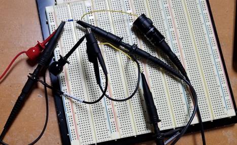
Experiment 1: 10:1 Probe Pic
Here
we will be showing what types of compensating probes we can get.
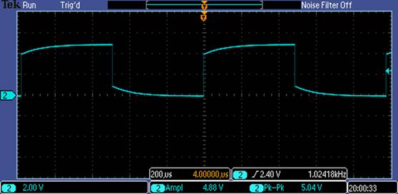
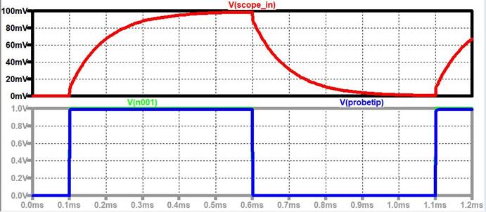
Undercompensated Probe:
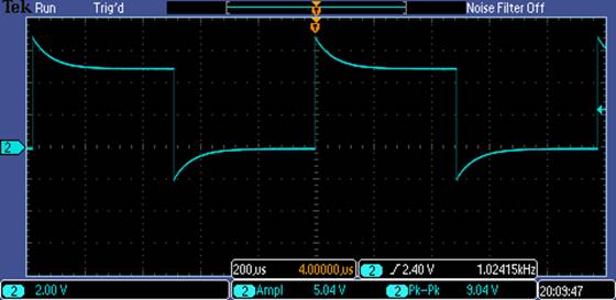
Overcompensated Probe:
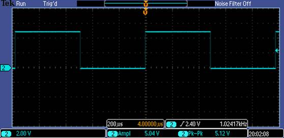
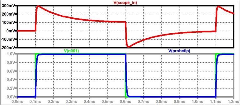
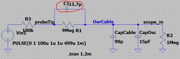
A Nice Compensated Probe:
Comment on the Probe:
The reason for
the undercompensated probe is for the capacitor being too small at the probe tip.
LTSpice: C1 =1pF
For the Overcompensated probe, the capacitor is too
big at the probe tip.
LTSpice: C1 = 50pF
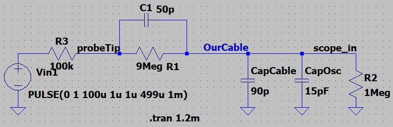
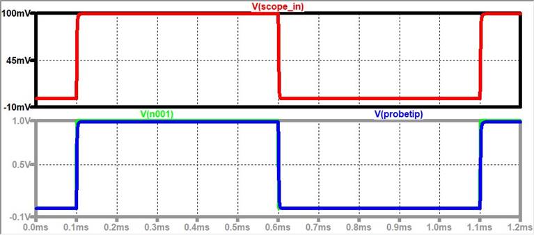
It makes sense
looking at the Overcompensated Probe
that the Output spikes up because if we assumed that C1 is super BIG, the current
will fully pass through the capacitor and the scope_in
voltage will equal the probe tip voltage.
Going back to
the Undercompensated Probe, the opposite
will occur and we will have it to where the voltage will slowly climb up.
For the Nice compensated probe, we will have a
clean signal at the scope_in that will look like what
is being seen at the probe tip.
Comment on the type of Scope
probe:
On the Scope,
we have the attenuation set to x10. The probe is a 10:1 probe, which means that
the voltage that travels through the cable is a 10th of the voltage
that is on the Probe Tip. Once the 10th of a volt gets to the input
of the oscilloscope, the oscilloscope does a simple math multiplier of 10 so
that the voltage that on the probe wire mimics the voltage that is at the Probe
tip.
Probe Tip Attenuation:
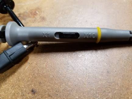
Here, this
special probe can either be set to x1 or x10 attenuation. If set to x1, the
voltage that is on the Probe tip will be the same on the probe wire cable. If
set to x10, then the impedance at the tip will drop the voltage to a 10th
of the voltage at the probe tip.
Oscilloscope Menu:
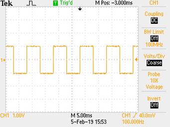
Here we can
see that our Probe attenuation is set to x10, and we are getting a 1V amplitude
read on the screen. This also means that the voltage that is actually received
by the oscilloscope is really a 10th of a voltage from the Probe
tip.
--------------------------------------------------------------------------------------------------
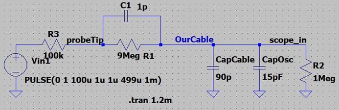
Maths and all That (Our Draft of The
Circuit):
So are we really telling the truth that there is at least 0.1 Volt
seen at the scope input?
Lets do some very simple math…
BEFORE THAT:
First we need some simple theory. We will be creating a voltage
divider, to where we want a 10th of a volt at the Output. So, we
start off with:
ZProbeTip = 9 * ZSmall
Assuming that
the Source Voltage and Probe tip are at the same Voltage potential (So very low
Current):
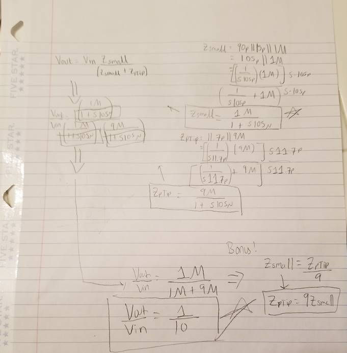
The whole
point of the hand calcs was to prove that if Ztip = 9
* Zsmall, that the voltage at the input of the scope
will always be 0.1*Vin.
IN OTHER WORDS:
RProbe = 9*RScope , ZCProbe = 9 * ZCsmall -->
CSmall
/ 9
---------------------------------------------------------------------------------------------------
Experiment 2: Solving for the
Parasitic Capacitance of the Cable & Probe
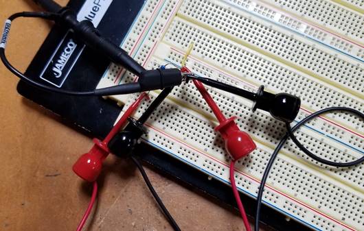
For
this Part of the experiment, we will be doing a super simple circuit, and that
is the RC time constant circuit.
By remembering
that one Time Constant is equal to about 63% of a voltage input, we can measure
the time constant on the Oscilloscope, and knowing the Resistance, we can experimentally
solve for the Capacitance of the cables.
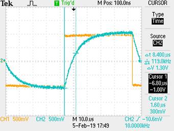
Oscilloscope Probe Capacitance:
R = 99.9k, Vin = 1V, freq = 10kHz
One time Constant = 1.6us
T = RC
C= T / R = 8.4u / 99.9k = 84.1pF
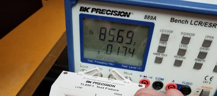
Oscilloscope Probe Cable
Measured Capacitance of Probe from LCR: 85.5uF
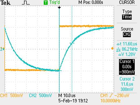
Power Cable Capacitance:
One Time constant = 11.6us
T =
RC,
C = T/R
= 11.6u / 99.9k = 116pF Power Cable
----------------------------------------------------------------------------------------------------
Experiment 3: Voltage Dividers!
For this
Experiment, we will be going high speed and testing out 2 different cables:
-An
uncompensated Power Cable,
-A nice
compensated Oscilloscope probe cable.
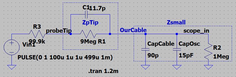
Here is our
Very simple circuit:
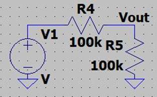
We will be doing
this at freq = 1MHz, so that we will be able to see
the effects of the cables’ capacitances.
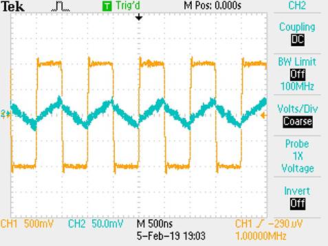
Uncompensated Power Cable:
Compensated Oscilloscope Probe
Cable:
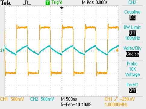
Observations:
For the
Uncompensated cable, we can see that there is some nasty noise that we do not
like in our cable, and that it is fairly accurate, however, we used about a 1-meter
wire, which can correlate to ~100pF/meter. This means, it will somewhat look
like our compensated probe, however, with some noise and maybe not as high of
an amplitude since it will need more time to charge up with the RC time constant.
Also, the Attenuation is set to x1.
For the
Compensated Probe cable, there is a cleaner signal and that it is a bit higher
than our uncompensated cable. The Impedance from the probe tip helped clean up
the signal so that we can be more accurate at the scope input. Even at a 10th
of a volt, this is very accurate and even though there can be some more fine
tuning at the probe, our result is acceptable since at a smaller capacitance,
we will get some zero points at the Megahertz range.
------------------------------------------------------------
How to implement a test point
on a PCB given the length of a cable:
For this, if
given we do not have a probe tip at the end of our cable, we can build our own
probe tip on the PCB! For that, we will set it up to where we have calculated
the capacitance of the cable and the scope input, and to make ZPCB = 9 * ZExternal, where ZPCB
is the Large impedance located on the printed circuit board, and ZExternal is the small impedances of the cable
and the oscilloscope scope input.