EE 420L Engineering Electronics II - Final Project
Authored by
David Flores
Email: flored6@unlv.nevada.edu
Due: May 8,
2019
Lab Description
For our Final
Project we are to design a voltage amplifier with a gain of 10, using certain
MOSFETs. For our design we went with the Push-Pull Amplifier. This amplifier is
to comply with certain specifications which include: driving a 1kΩ
resistor, input resistance greater than 50k, as fast as possible design, as
large output swing as possible, and cannot draw more than 1 mA
from a 9V supply voltage under quiescent conditions.
Lab Instructions
Project – design a voltage amplifier
with a gain of 10 using either the ZVN3306A or ZVP3306A (or both) MOSFETs and as
many resistors and capacitors as you need. You should try to get as fast a design as
possible driving a 1k load, with an input resistance greater than 50k, with as
large of output swing as possible. AC coupling input and output is okay as long
as your design can pass a 100 Hz input signal. Your report, in html, should
detail your design considerations, and measured results showing
the amplifier's performance. Your design can draw no more, under quiescent
conditions (no input signal), than 1 mA from a +9 V
supply voltage. Your report is due at the beginning of lab on Wednesday, May 8. Access
to your CMOSedu.com lab accounts will be removed at this time.
Final Project:
We start off
by picking a certain amplifier that we could use to meet all the
specifications. For that we went and reviewed past labs where we worked on
certain amplifiers. Specifically in lab 6 we saw that we had used the push-pull
amplifier we went with this design because it can be used as a transimpedance
amplifier because it has a high gain and can drive a load.
One of the important
parameters of this Project is that the design must draw less than 1mA from a 9V
VDD power supply. The input resistance must be greater than 50k.
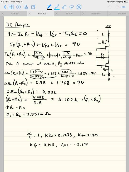
These
parameters need to be met so we set our current at 0.8mA not too low in case we
need more current but not 0.9mA so that is won't accidently go to high.
As for the input
resistance the push-pull amplifier usually has a large input resistance at
about 100k or more. This is so that no AC current goes back through Vin. When
we model the current for our hand calculations we can assume there is zero AC
current across that 100k+ resistor.
Hand Calculations:
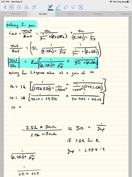
AC Analysis Solving For Gain
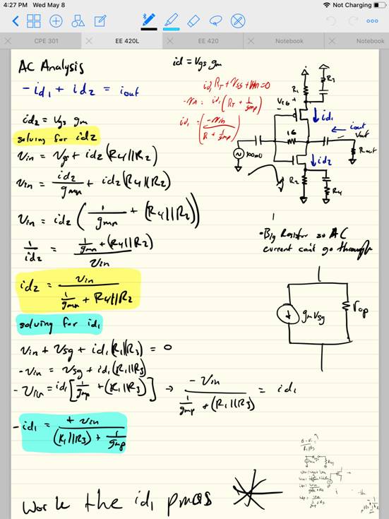
DC Analysis to solve for our Resistors
For the hand
calculations I got a gain of 17 compared to the gain of 10 on the Ltspice simulation. This happens because the circuit we
made is a bit unstable and can have issues.
NOTE** I tried solving for a bigger gain for my hand calculations
say a gain of 12 so that I would get a gain of 10 on the breadboard. This was
not the correct approach because not only was the design very unstable but if
we messed with the resistor sizes we would jump pass our current limitations.
So for future reference I would say to add another stage. Using this Push-Pull
could still work but adding another stage with additional push pull or source
followers could really help me all of the specifications.
LTspice Simulations:
Ltspice Schematic for our Push Pull
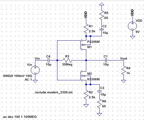
Transient analysis to show gain of 10 AC analysis to show gain
at different frequencies
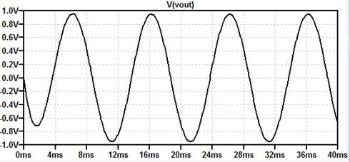
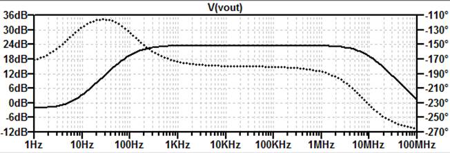
The results
here show that at a frequency of 100Hz we get a gain of 20dB or 10 which is
what we want but it is really unstable a small offsets in resistor values or
frequency can cause a big change in our gain. So if we needed to improve that specifically we would make it
so that it is flat from the DC gain up until the drop off closer to our unity
gain frequency. Some ideas that could help this specifically is probably adding
a source follower so that the gain is not all in one jump. This way we wouldn't
have to worry so much about our resistor values and being so precise.
Lab Results:
Oscilloscope Results
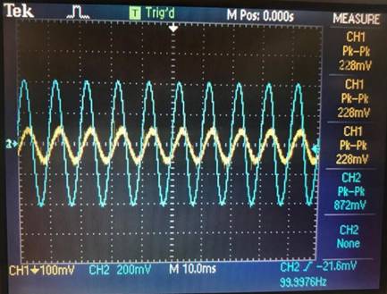
A gain of
about 8.2 was as good as I could get it with the parameters we needed to meet
and this specific topology. If I lowered the resistor values anymore so that we
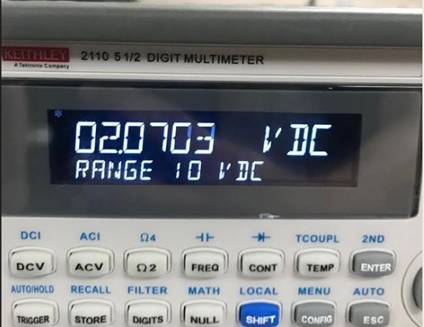
could get a better gain the current would go past the limitations set. As we
can see from the Multimeter are results are at their
max for this specific topology.