EE 420L Engineering Electronics II - Lab 7 Design of an Audio
Amplifier
Authored by
David Flores
Email: flored6@unlv.nevada.edu
Due: April
3, 2019
Lab Description
For this lab
we were to design an audio amplifier that has a frequency range of about
100Hz-20kHz with an input is an audio signal from an MP3 the Output of the design
in an 8ohm resistor which is the speaker.
Pre-lab
Lab Instructions
Design an audio
amplifier (frequency range from roughly 100 Hz to 20 kHz) assuming
that you can use as many resistors, ZVN3306A transistors, and ZVP3306A
transistors as you need along with only one 10 uF
capacitor and one 100 uF capacitor. Assume that the
supply voltage is 10 V, the input is an audio signal from an MP3 player (and so
your amplifier should have at least a few kiloohms input resistance), and the
output of your design is connected to an 8-ohm speaker (so, ideally, the output
resistance of your amplifier is less than 1 ohm).
- Your
lab report should detail your thoughts on the design of the amplifier
including hand-calculations.
- A
good place to start is with the push-pull amplifier characterized in lab
6.
- Simulate
your design. Document the results in your lab report.
- Build
and test your design.
- Document
the performance of the design including power dissipation, output swing, input
resistance, output resistance.
Ensure that your html lab report includes your name, the
date, and your email address at the beginning of the report (the top of
the webpage).
When
finished backup your work.
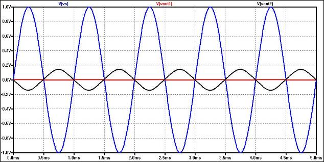
Below
is a comparison between driving a speaker without (red, Vout1) and with (black,
Vout2) an audio amplifier. The source resistance is 10k meaning that the source
can supply 1 V (blue, Vs) at 100 uA maximum. The
simulation files used to generate this figure are found in lab7_sims.zip.
Lab Report:
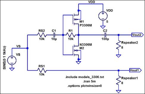
For this lab we made a push pull audio amplifier. We
changed some of the components to better our output with an input of an aux
cord from the computer, so we could output out of the speaker. We know from previous
labs that if increase R1 in the push pull circuit we increase the gain this is
needed so that the audio signal produced by the MP3 can be heard by a human. We
also designed it so that we could have a range of frequency from 100Hz to
20kHz. Here are Hand Calculations from the modified circuit above.
Hand Calculations:
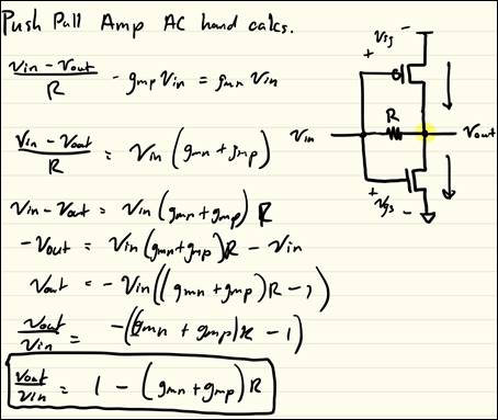
With the hand calculations we can see that to increase the
voltage gain which increases volume we need to increase the resistor between
Vin and Vout. This will also increase the power
consumption. To increase the power consumption more we
need to decrease the Rs Resistor this limits the Current through the Push Pull.
So we increased R1 to 100k and decreased R2 to 2k. We
used an output resistance of 8 ohms because that is how much the speaker was we
could have used a different speaker with 25 ohms resistance
but we would need more current through that resistor which means a bigger
voltage drop. Here are our LTSpice from the circuit
above except modified as stated previously.
LTSpice Results for Audio Amplifier
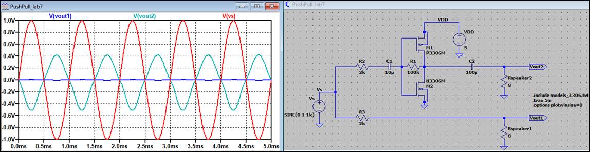
The red waveform is our sinusoidal at 1V Pk-Pk
which is representing what our input audio signal would be. The blue waveform
is our Vout1 which is our output with no amplification. Our turquoise waveform
is Vout2 which is our amplified output.
As we can see from our results in comparison to the previous circuit we
did get a bigger amplification. There are some draw backs to this design
though, the outputted signal can sometimes become a bit noisy and it shows that
the waveform is not as smooth on LTSpice.
Oscilloscope Results of above circuit at 1kHz
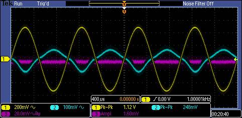
Here we simulated the above circuit we got our yellow signal which is our
Vin = 1V Pk-Pk at 1kHz. The blue signal is our
Amplified signal Vout2 = 248mV. The purple signal is our unamplified signal
Vout1 = 2.4mV (VDD = 5V).
Frequency Range
From 100Hz-200kHz.
For these results we used Vin as 1V Pk-Pk and
at 5V VDD.
Oscilloscope Results at 100Hz Oscilloscope Results at 20kHz
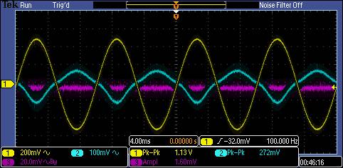
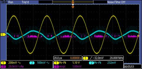
Here at 100Hz we got a gain of 272mV and the unamplified signal gave us
1.6mV. At 20kHz we got a gain of 232mV and the unamplified signal gave us
1.6mV.
Power Dissipation
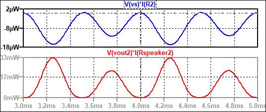
Here is the power dissipation from LTSpice
ideally we would want to have a larger power
dissipation but for the push pull design the best option was to lower it.
Final Results:
https://www.youtube.com/watch?v=xbiRdW42jdU