EE 420L Engineering Electronics II - Lab 5
Authored by
David Flores
Email: flored6@unlv.nevada.edu
Due: March
13, 2019
Lab Description
For this lab
we are going to solve for the frequency response of a circuit and verify experimentally.
We also made a triangle waveform using a square wave input.
Pre-lab
- Watch
the video op_amps_III,
review op_amps_III.pdf (associated notes),
and simulate the circuits in op_amps_III.zip.
- Read
the write-up seen below before coming to lab.
Lab Instructions
Again, this lab will
utilize the LM324 op-amp (LM324.pdf).
For the following questions and experiments assume VCC+ = +5V and
VCC- = 0V.
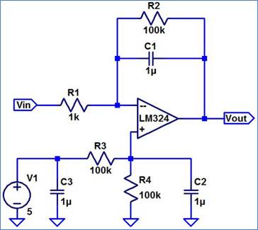
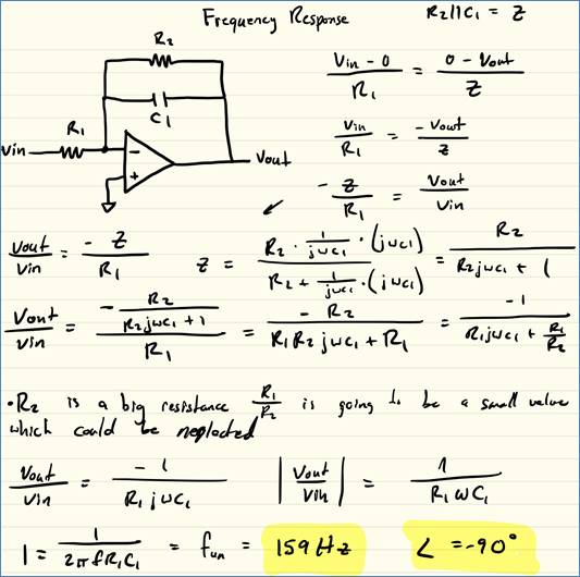
- Calculate the frequency response of the following circuit. Ensure you
show your clear hand calculations.
- What
can you neglect to simplify the calculation?
- Does
the circuit work if you remove the 100k? Why or why not?
- Does
the 100k have much of an effect on the frequency response?
- Verify
your calculations with experimental results.
- Show,
at the unity-gain frequency of the integrator, that the input and the
output have the same peak values.
- Is
the phase shift between the input and the output what you expect? Why or
why not?
- Next,
design, simulate, and build a square-wave to triangle wave generation
circuit.
- Assume
the input/output frequency is 10 kHz and the output ramp must swing from 1
to 4 V centered around 2.5 V.
- Show
all calculations and discuss the trade-offs (capacitor and resistor
values, input peak, min, and average, etc.)
Experiment 1:
- Calculate the
frequency response of the following circuit. Ensure you show your clear
hand calculations. What can you neglect
to simplify the calculation?
·
Does the
circuit work if you remove the 100k? Why or why not?
If the 100k resistor is removed the circuit should work,
there might be some problems since the Op-Amp is not ideal. It needs that big
resistor so that it can pass the offset voltage. The output might clip if the
input signal too big.
·
Does the 100k
have much of an effect on the frequency response?
The R2 100k resistor does not really affect the frequency it
is so bit that it is not really comparable to the
smaller 1k resistor R1. The resistor acts like an open or infinite resistance.
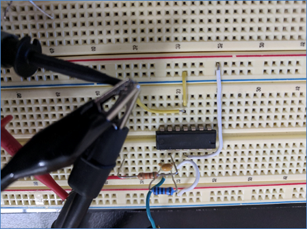
Verify your
calculations with experimental results.
Oscilloscope results with
R2 Oscilloscope
results with R2 removed
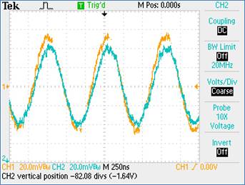
If we remove the resistor R2 form the circuit, we are removing the DC offset
from the output. We can see in the results that CH2 is not in the same position.
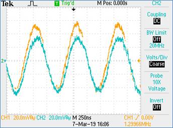
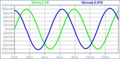
Show, at the
unity-gain frequency of the integrator, that the input and the output have the
same peak values.
We can see above that the waveforms have about the same peak voltages
at a 1.3MHz
![]()
Ltspice
simulation showing same peak values
We can
see that the waveforms have about the same amplitudes.
Is the phase
shift between the input and the output what you expect? Why or why not?
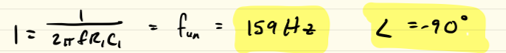
We calculated the phase shift to be
-90![]() This happens because of the capacitor.
This happens because of the capacitor.
Experiment
2: Triangle Waveform
Next,
design, simulate, and build a square-wave to triangle wave generation
circuit. Assume the input/output frequency is 10 kHz and the output ramp
must swing from 1 to 4 V centered around 2.5 V.
![]()
![]()
![]()
![]()
Show all
calculations and discuss the trade-offs (capacitor and resistor values, input
peak, min, and average, etc.)
Oscilloscope results of our
triangle waveform
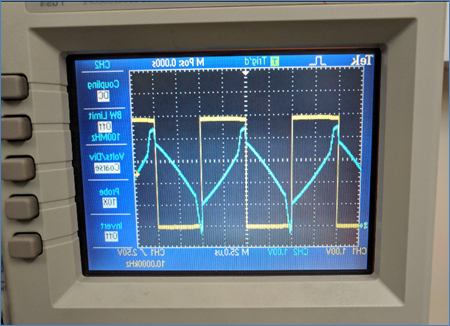
We used a smaller
capacitor which seemed to give us a better result, but we would need a bigger
resistor. There will generally be more noise at these high capacitances with different
components.