EE 420L Engineering Electronics II - Lab 4
Authored by
David Flores
Email: flored6@unlv.nevada.edu
Due:
February 27, 2019
Lab Description
For this lab we are
going to solve for bandwidth for inverted and non-inverted op-amps with a set
unity frequency gain and a gain at 1,5, and 10. We also be looking into the
slew-rate and how it works with both a square wave input and a sinusoidal
input.
Pre-lab
- Watch the
video op_amps_II,
review op_amps_II.pdf (associated notes),
and simulate the circuits in op_amps_II.zip.
- Read
the write-up seen below before coming to lab.
Lab Instructions
Again, this lab will utilize the LM324 op-amp (LM324.pdf).
For
the following questions and experiments assume VCC+ = +5V and VCC- = 0V.
- Estimate,
using the datasheet, the bandwidths for non-inverting op-amp topologies having
gains of 1, 5, and 10.
- Experimentally
verify these estimates assuming a common-mode voltage of 2.5 V.
- Your
report should provide schematics of the topologies you are using for
experimental verification along with scope pictures/results.
- Associated
comments should include reasons for any differences between your
estimates and experimental results.
- Repeat
these steps using the inverting op-amp topology having gains of -1, -5,
and -10.
- Design
two circuits for measuring the slew-rate of the LM324. One circuit should
use a pulse input while the other should use a sinewave input.
- Provide
comments to support your design decisions.
- Comment
on any differences between your measurements and the datasheet’s
specifications.
Ensure
that your html lab report includes your name, the date, and your email
address at the beginning of the report (the top of the webpage).
When
finished backup your work.
Experiment 1: Non-Inverting
Op-Amp
Estimate, using the datasheet, the bandwidths for non-inverting op-amp
topologies having gains of 1, 5, and 10.
Experimentally verify these estimates assuming a common-mode
voltage of 2.5 V.
- Your
report should provide schematics of the topologies you are using for
experimental verification along with scope pictures/results.
- Associated
comments should include reasons for any differences between your
estimates and experimental results.
![]()
From the datasheet we can see that the Gain Bandwidth Product is
equal to about 1.3MHz. This is also known as the unity gain frequency (fun).
With a gain of 1 the we would have ![]() which means that the Bandwidth is equal to the
unity gain frequency which is 1.3MHz
which means that the Bandwidth is equal to the
unity gain frequency which is 1.3MHz
For a gain of 5 we would have ![]() bandwidth is equal to 260kHz.
bandwidth is equal to 260kHz.
For a gain of 10 we would have ![]() bandwidth is equal to 130kHz.
bandwidth is equal to 130kHz.
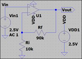
Gain of 1:
Schematic 1:
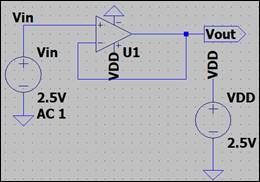
Oscilloscope Measurement at a Gain of 1
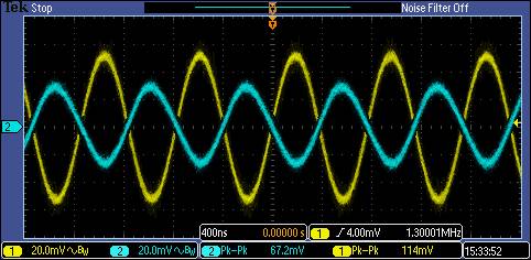
Output is
our blue waveform and it is at a magnitude of about 0.707V~67.2mVthis value
would put it at 3dB which is where we measure our bandwidth but for this
specific experiment we do not have a roll-off like normal since it’s a gain of
1 so the bandwidth is the unity gain frequency.
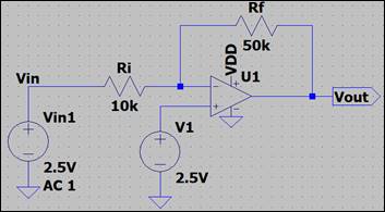
Gain of 5:
Schematic
2
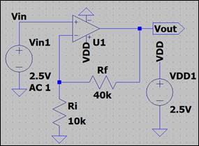
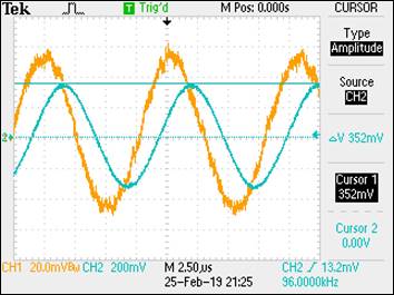
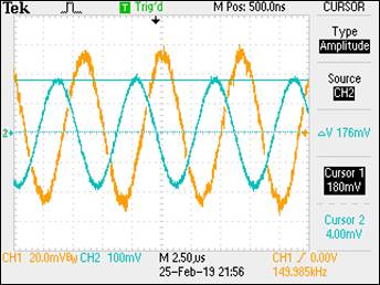
Oscilloscope Measurement at a Gain of 5
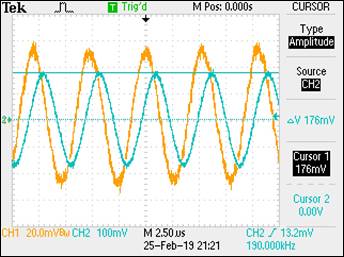
Here the
results of the oscilloscope show that the roll-off point is at about 3dB or
190kHz. For this experiment we had a bit of error this is due
to the fact that we were not using an ideal op-amp. The hand
calculations were made assuming we had an ideal op-amp
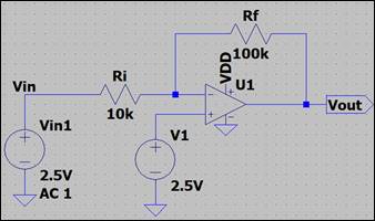
Gain of 10:
Schematic 3:
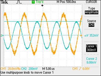
Oscilloscope Measurement at a Gain of 10
Output is
our blue waveform the magnitude is about 0.707V at a frequency of 96kHz. The
estimated calculations are not that close to the results of the waveform again
the ideal op-amp can affect the output waveforms.
Experiment 2: Inverting Op-Amp
- Repeat
these steps using the inverting op-amp topology having gains of -1, -5,
and -10.
For this
experiment we will be doing the same exact thing as experiment 1 except the
op-amp topology is inverted. This is the same experiment except its inverted so
only results will be provided.
![]() so
so ![]()
Gain of -1: ![]()
Gain of 5:![]()
Gain of 10: ![]()
Gain of -1:
Schematic 4:
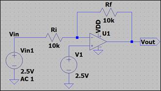
Oscilloscope Measurement at a Gain of -1
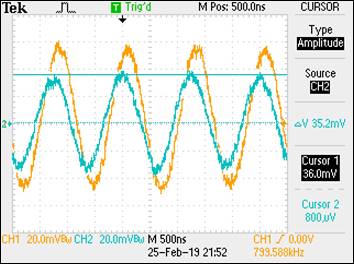
Bandwidth = 800kHz
Gain of -5:
Schematic 5:
Oscilloscope Measurement at a Gain of -5
Bandwidth = 150kHz
Gain of -10:
Schematic 6:
Oscilloscope Measurement at a Gain of -10
Bandwidth = 83kHz
Experiment 3: Slew Rate
Design two circuits for measuring the slew-rate of the LM324. One
circuit should use a pulse input while the other should use a sinewave input.
- Provide
comments to support your design decisions.
- Comment
on any differences between your measurements and the datasheet’s
specifications.
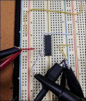
In this
experiment we built two circuits a unity follower circuit for both, but one has
a square input and the other has a sinusoidal input.
Non-inverted with AC input and 2.5V DC offset Oscilloscope Measurement square
wave input
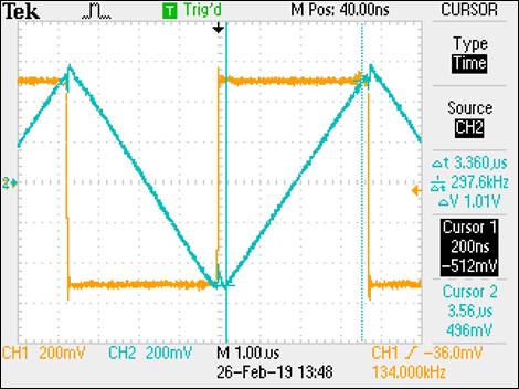
We
have a rise of 1.01V and a run of 3.36us =0.3V/us
Square Wave
Slew Rate Hand Calculations:
![]()
Here we can see
that we designed a circuit that can show the slew-rate the “rising” voltage is
too much for the “running” time to keep up so instead of showing a square wave
like it should. Instead it shows a triangle wave. We noticed that as the input
voltage increases we get a triangle wave and then after that it starts turning
into a sinusoidal which means that the peak voltages are getting cut off
because there is not enough time to keep up with the voltage. The data sheet
says that we have a slew rate of 0.4V/us which is close to our experimental value of 0.3V/us.
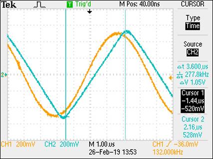
Oscilloscope
Measurement Sinusoidal input
![]()