Lab 5 - ECE 420L
Authored
by Kyle Butler, butlerk2@unlv.nevada.edu
3/13/2019
Pre-lab work:
- Watch the video provided and review the associated notes, and simulate the circuits in op_amps_III.zip
- Read the write-up seen below before coming to lab.
Lab work:
- Calculate the frequency response of the following circuit. Ensure you show your clear hand calculations.
- What can you neglect to simplify the calculation?
- Does the circuit work if you remove the 100k? Why of why not?
- Does the 100k have much of an effect on the frequency response?
- Verify your calculations with experimental results.
- Show, at the unity-gain frequency of the integrator, that the input and the output have the same peak values.
- Is the phase shift between the input and output what you expect? Why or why not?
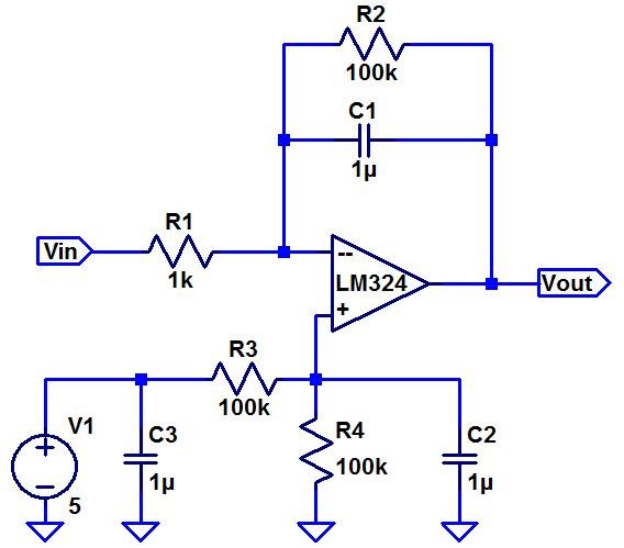
- Next, design, simulate, and build a square-wave to traingle wave generation circuit.
- Assume the input/output frequency is 10KHz and the output ramp must swing from 1 to 4V centered around 2.5V.
- Show all calculations and discuss the trade-offs(capacitor and resistor values, input peak, min, and average, etc)
Frequency Response
Hand calculations:
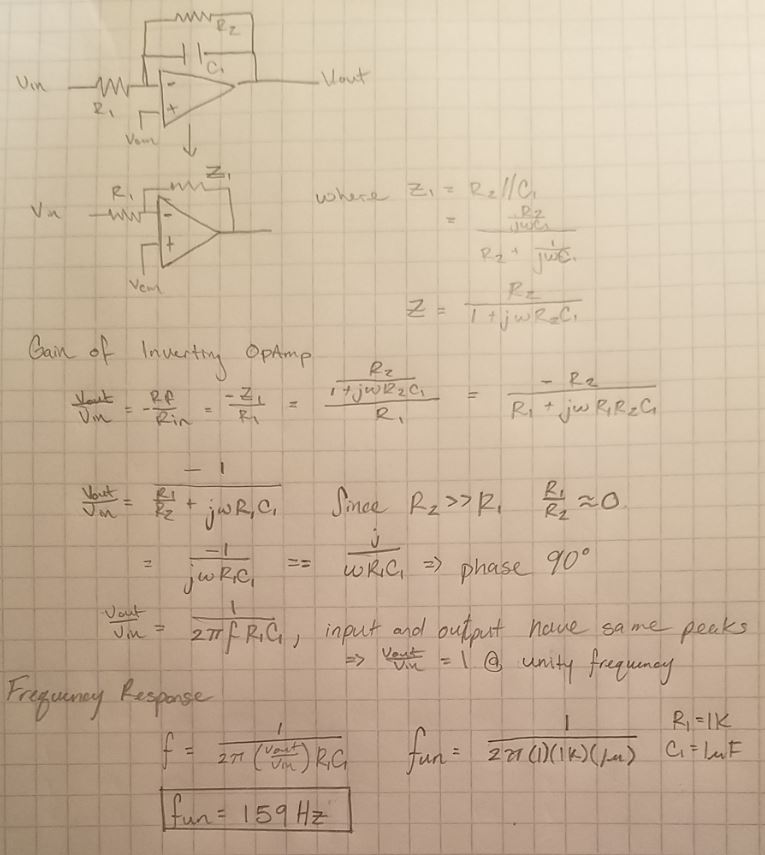
What can you neglect to simplify the calculation?
The 100k resistor, R2, can be neglected because it is much larger then the 1k resistor, R1.
The leaves the frequency response depedanty on R1, C1, and Gain.
Does the circuit work if you remove the 100k? Why or why not?
It would not operate correctly. The DC gain is dependant on the impedance between the inverting input and the output.
Removing the 100k would leave just the capacitors impendance for the DC gain, which is inifite in DC causeing the output
to hit the rails of the opamp.
Does the 100k have much of an effect on the frequency response?
Considering the hand calculations the 100K does not effect the frequency response, this is because the resistors impedance
is much larger than the capacitor.
Experimental Results
Unity Gain of 159Hz
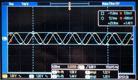
Both the input and output have a peak of approx. 1.3V
Is the phase shift between the input and output what you expect? Why or why not?
Yes, the hand calculations show an expected phase of 90 degrees. The image above shows a phase shift of approx. 90 degree.
Squarewave to Trianglewave circuit
Hand calculations:
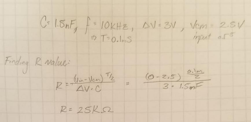
Simulation
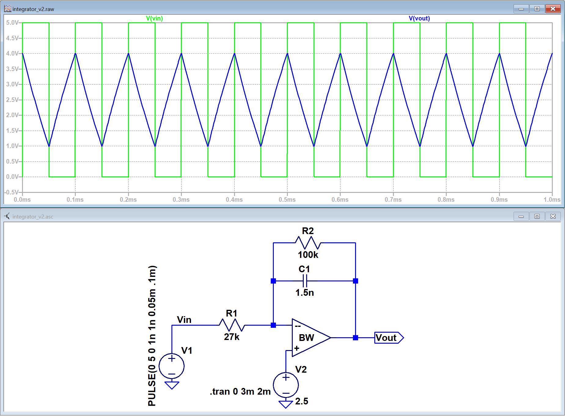
Using 27K for the resistor value gives a better output response, the 25K has the traingle wave from .9V to 4.1V.
Experimental Results:
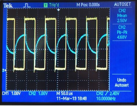
The output is not ideal, this could be because of the tolerance of the components used.
Trade off's:
If the selected resistor is too small, the DC gain will be too large.
Otherewise if the resistor is too large and the DC gain will be too small.
Return to butlerk2 EE 420L Reports
Return to EE 420L Labs