Lab 7: Audio Amplifier ECE 420L
Authored By: Joey Yurgelon
Email: yurgelon@unlv.nevada.edu
March 29, 2015
Pre-lab Work:
Lab Description:
- Students
will understand how build, test, and analyze an audio amplifier.
Lab Requirements:
Design an audio amplifier (frequency range from roughly 100 Hz to 20
kHz) assuming that you can use as many resistors, ZVN3306A transistors,
and ZVP3306A transistors as you need along with only
one 10 uF capacitor and one 100 uF capacitor. Assume that the supply
voltage is 10 V, the input is an audio signal from an MP3 player (and
so your amplifier should have at least a few kiloohms input
resistance), and the output of your design is
connected to an 8-ohm speaker (so, ideally, the output resistance of
your amplifier is less than 1 ohm).
- Your lab report should detail your thoughts on the design of the amplifier including hand-calculations.
- A good place to start is with the push-pull amplifier characterized in lab 6.
- Simulate your design. Document the results in your lab report.
- Build and test your design.
- Document the performance of the design including power dissipation, output swing, input resistance, output resistance.
Ensure that your html lab report includes your name, the date, and your
email address at the beginning of the report (the top of the
webpage).
Experimental Results:
Exercise #1: Design and build an audio amplifier.
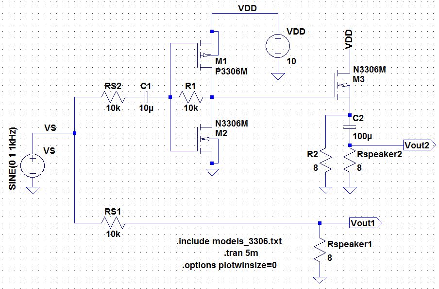
NOTE: M3 in the simulation is the added NMOS output stage which was added to increase gains in the circuit.
- My
partner and I started out with the push-pull amplifier that was
presented in Lab 6 as well as in today's lab. After building it,
however, we did not have enough gain to really drive our speaker.
Despite having the volume turned up completely, we were only getting a
little bit out of the speaker. We were able to check via simulations
that our output/input resistances were at respectable values. To
increase the gain of the amplifier without using another capacitor, we
were able to add another NMOS transistor at the output, and change the
resistors located in the source to filter out the DC bias while still
giving us a path to ground as well as the small output resistance. The
results are listed below.
- As far as the calculations for the push-pull amplifier, one
can see that by inspection, the gain will be the sum of the resistances
seen looking into the source's of the transistors multiplied by the
feedback resistor. It can be seen as follows: Vout = Rf*(gmp + gmn)*Vin.
- We
took a shot of the power-supply voltage and current consumption to get
an idea of how thirsty our circuit actually was. From the picture
listed below, we can see that our power consumption was
(10.7V)*(0.320A) = 3.434W of power. Our simulations were very
comparable at (5.12W)/(sqrt(2)) = 3.62W.

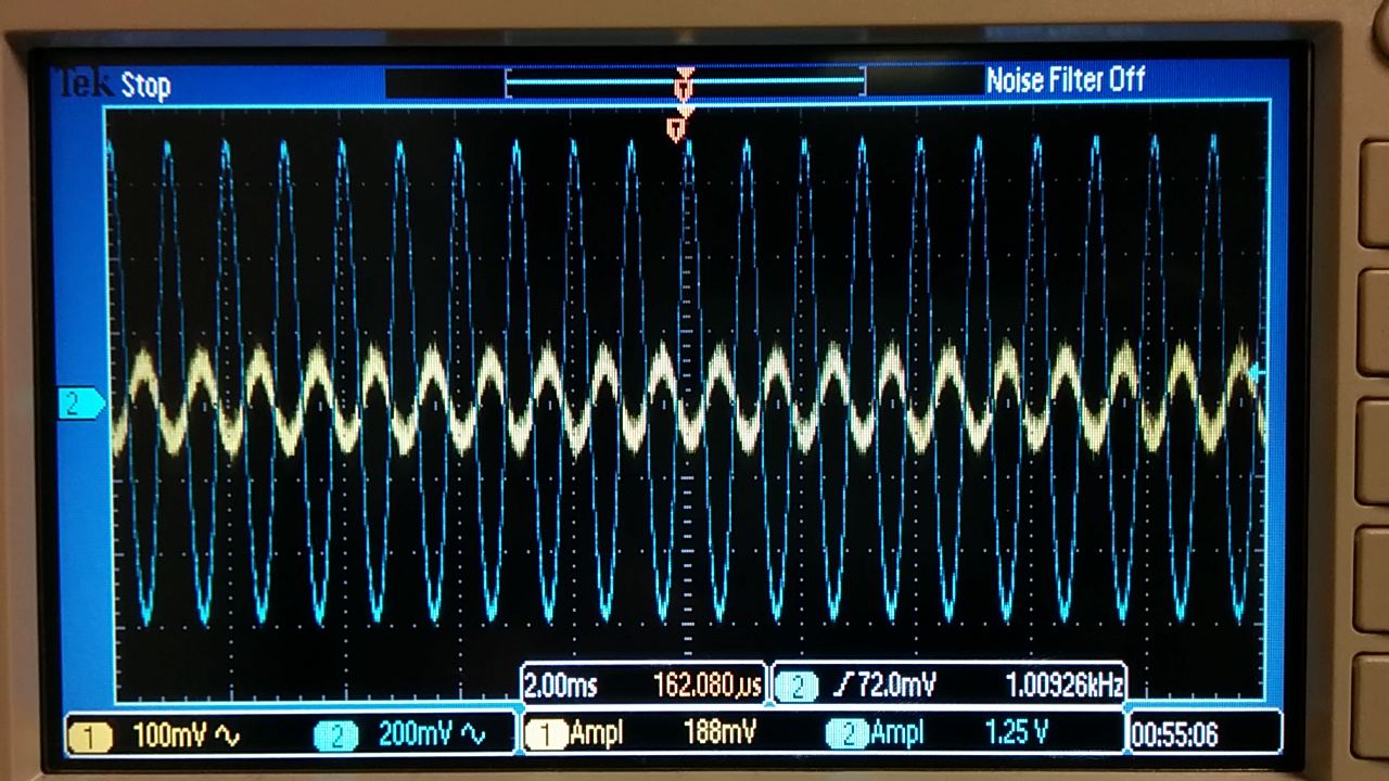
Audio Amplifier Schematic | Audio Amplifier Output Waveforms |

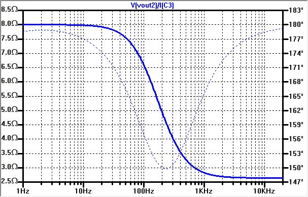
Audio Amplifier Output Resistance | 
Audio Amplifier Input Resistance |

Audio Amplifier Simulated Power Consumption | 
Experimental Power Consumption |

Audio Amp. without Added NMOS Output Stage ~1x | 
Audio Amp. With Added NMOS Output Stage ~6.64x |
Return to EE 420L Labs


