Lab 4: Op-Amps II, Gain-Bandwidth Product and Slewing ECE 420L
Authored By: Joey Yurgelon
Email: yurgelon@unlv.nevada.edu
February 19, 2015
Pre-lab Work:
Lab Description:
- Students
will understand the bandwidth and gain relation of op-amps as well as their various speed limitations.
Lab Requirements:
- Repeat these steps using the inverting op-amp topology having gains of -1, -5, and -10.
- Design
two circuits for measuring the slew-rate of the LM324. One circuit
should use a pulse input while the other should use a sinewave input.
- Provide comments to support your design decisions.
- Comment on any differences between your measurements and the datasheet’s specifications.
Experimental Results:
Exercise #1: Estimate, using the datasheet, the bandwidths for non-inverting op-amp topologies having gains of 1, 5, and 10.
- The
GBP of the LM324 is listed as 1.3MHz. This is when the gain is 1x. It
would soon follow suit that by increasing the gain, the bandwidth must
go downwards. The estimated values are seen below.
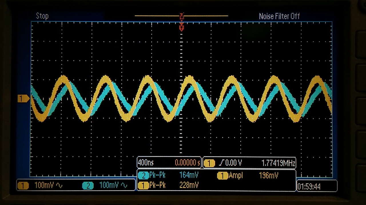
Exercise #2: Experimentally verify these estimates assuming a common-mode voltage of 2.5V.
- Since this configuration is non-inverting, we expect that the estimates
made in the previous exercise will hold relitively true experimentally
as well. This, however, was not exactly the case. We had quite a bit of
issues getting this circuit to function as intended, but when we did,
we received values much greater than those listed in the datasheet. We
could only assume that the op-amp that was used could of been the cause
and was surely an annomoly. The various 3dB frequencies are varied
gains are listed in the table below.
| 3dB Frequency | Gain |
| 1.77 MHz | 1x |
| 337.9 kHz | 5x |
| 203.4 kHz | 10x |

Non-Inverting Topology and Circuit Layout | 
Non-Inverting: 1x Gain: 1.77 MHz 3dB Point |

Non-Inverting: 5x Gain: 337.9 kHz 3dB Point
| 
Non-Inverting: 10x Gain: 203.4 kHz 3 dB Point |
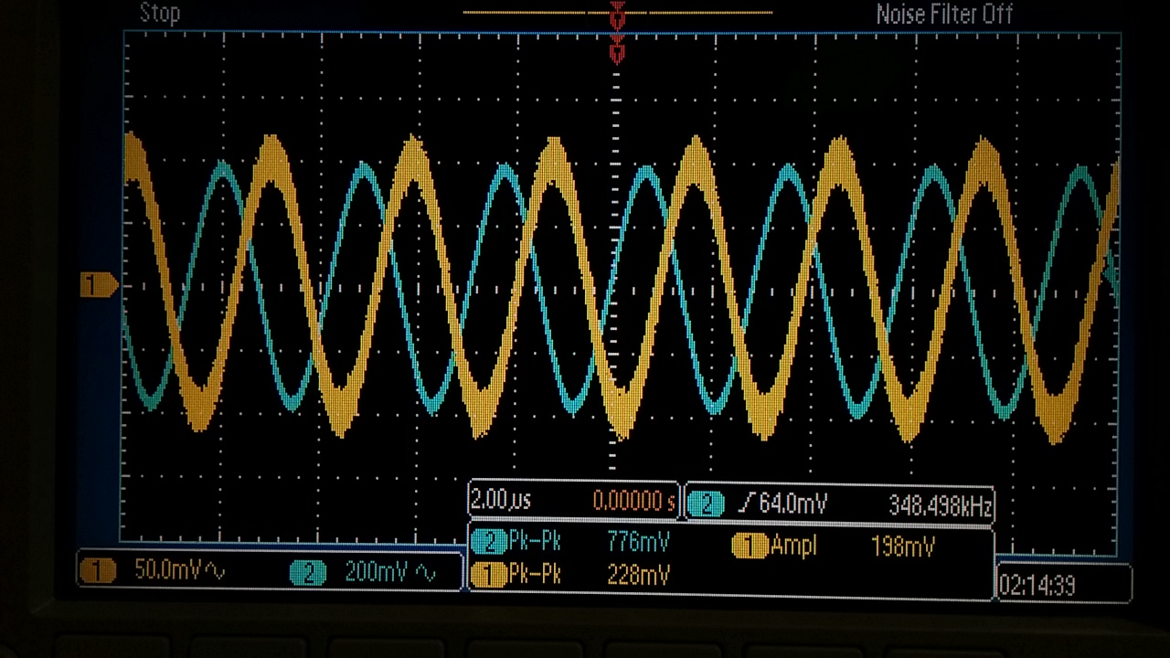
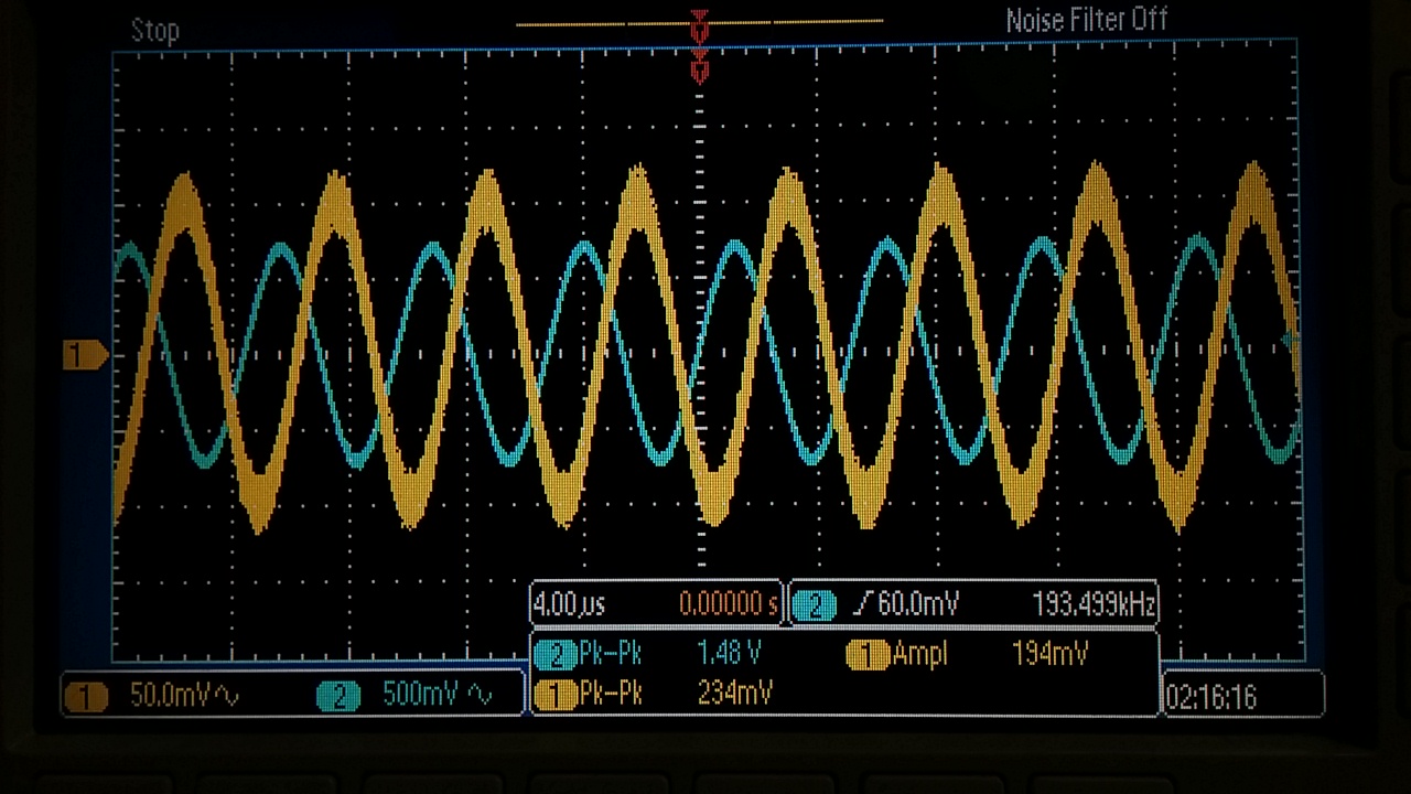
Exercise #3: Repeat these steps using the inverting op-amp topology having gains of -1, -5, and -10.
- Since
we are using a inverting topology in this case, the calculation for the
BW is slightly different. The correct formula would be as follows:
abs(R2/R1 + 1)*BW = GBP. The theoretical BW values can be seen
below. In our experimental calculations, we can see that once the
gain increases to approximately 5, the corrected formula does not have
the same affect as it did at the lower gain values.
| 3 dB Frequency | Gain |
| 1.26 MHz | 1x |
| 348.4 kHz | 5x |
| 193.4 kHz | 10x |

Inverting Topology and Circuit Layout | 
Inverting: 1x Gain: 1.26 MHz 3 dB Point |

Inverting: 5x Gain: 348.3 kHz 3 dB Point | 
Inverting: 10x Gain: 193.4 kHz 3 dB Point |
Exercise #4: Design
two circuits for measuring the slew-rate of the LM324. One circuit
should use a pulse input while the other should use a sinewave input.
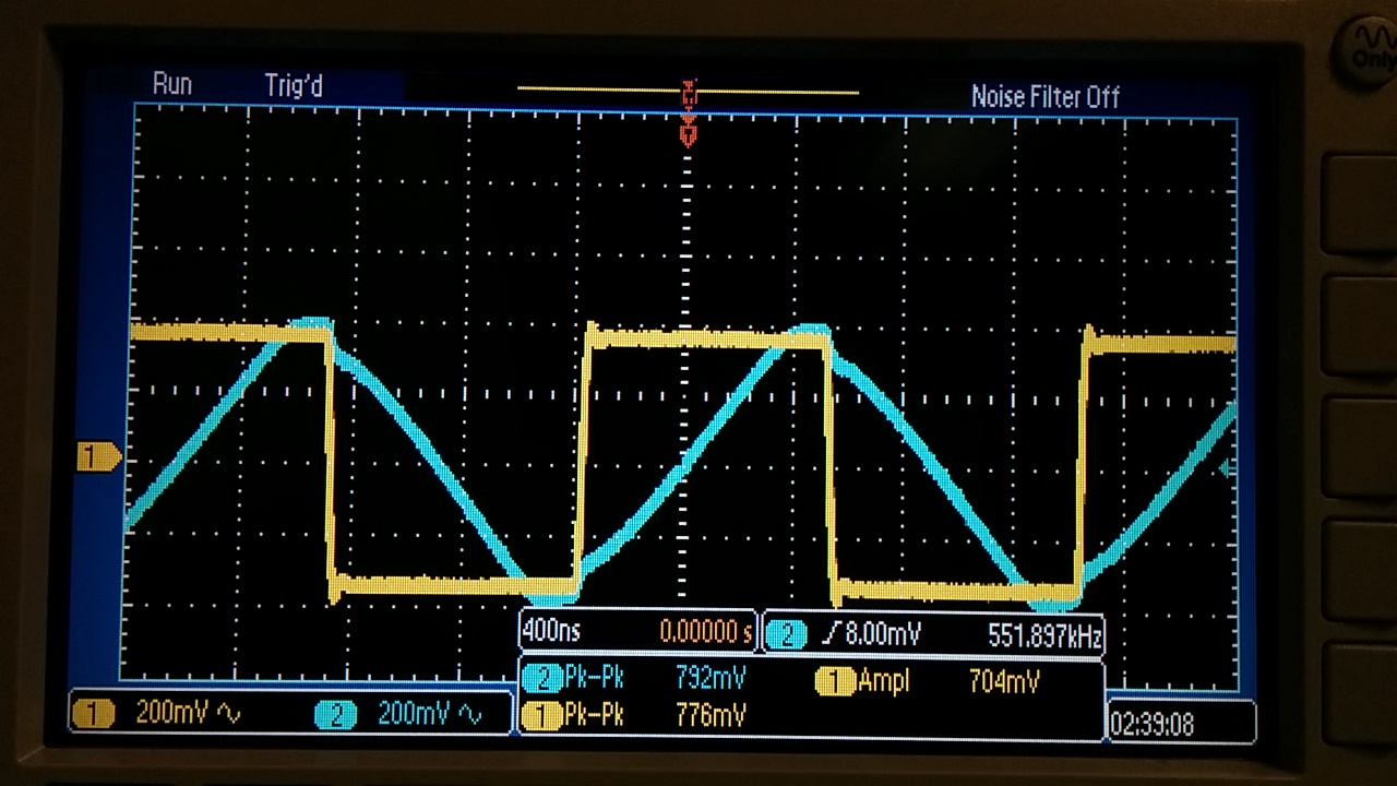
- In
the following two pictures, one can see that with an increase in the
amount of voltage being switched at the output, the lower the frequency
needed to cause a slew rate issue. In both cases, we increased the
innput voltage as high as possible without saturating, and then
increased the input frequency till the output began to become slew
limited. The hand calculations as presented in the video are rederived
below. As for experimental testing, we used a non-inverting topology
with a 10x gain. This design consideration was taken due to the fact
that we would expect nearly a cosine, or a phase shift if we started to
become slew limited. This can be seen in the sine wave picture below.
The blue line which represents the output cannot keep up with the input
which produces the triangular wave with an associated phase shift as
expected. If one were to compare the input voltage of the sinewave
divided by the period of the input signal, one can see that our slew
rate is roughtly 1.24 V/uS which is comparable to that of the op-amp
spec sheet of 0.4 V/uS. Our calculations of the square wave input,
however, become 0.428 V/uS.
Return to EE 420L Labs


