Lab 5 - EE 420L Engineering Electronics II
For the following questions and experiments assume VCC+ = +5V and VCC- = 0V.
| Simulation
Circuit |
Ft
= 157 Hz |
Part 2:
| Sinusoidal
Signal, Ft = 159 Hz |
Square
Wave Signal, Ft = 159 Hz |
 |
 |
Conclusion:
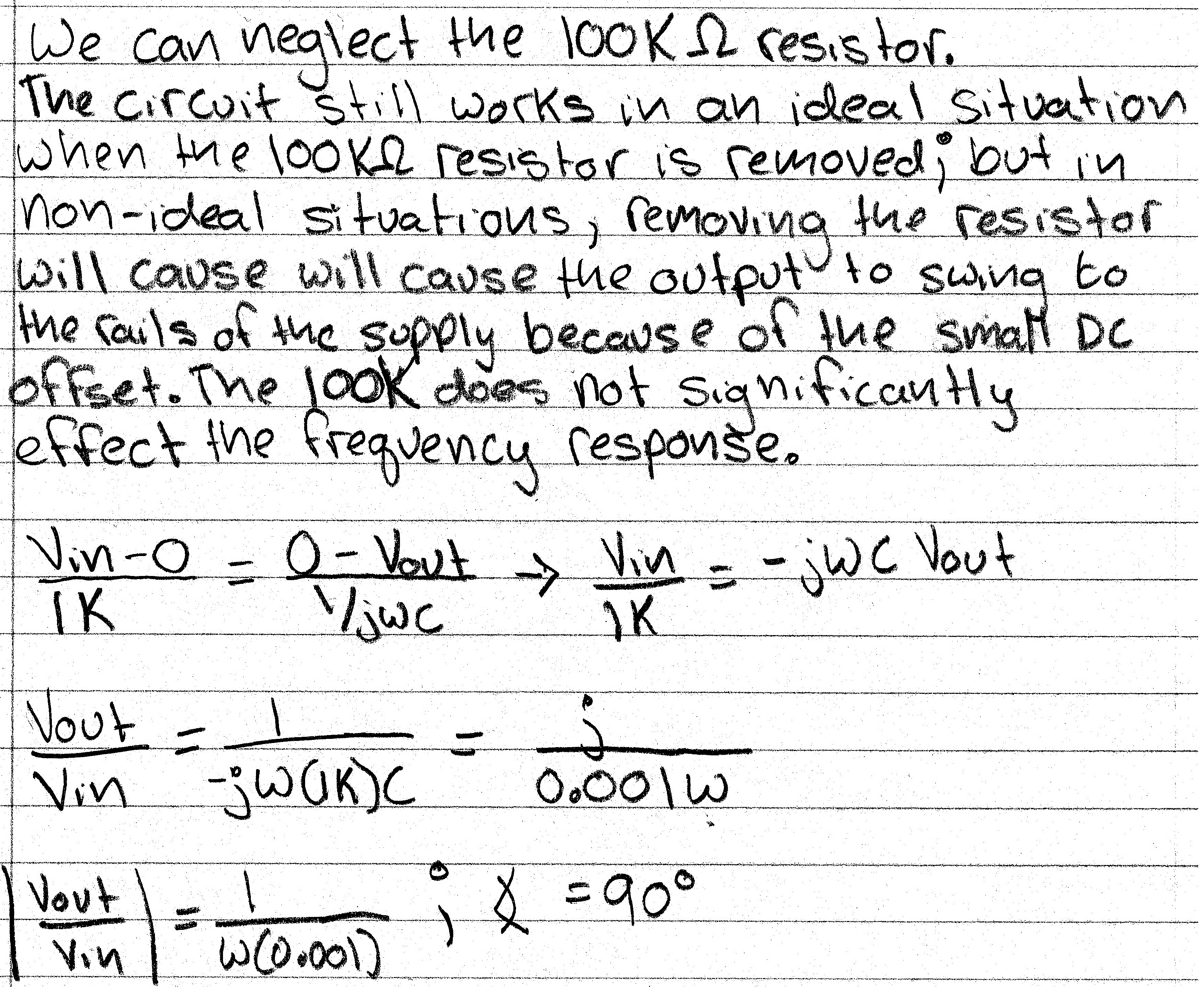
The calculated unity-gain frequency is Ft = 159 Hz. In the sinusoide above, we can see that the peak values are approximately
equal. However, in the square wave signal above, we see that the output (triangle wave) has a peak value greater than the input.
The
two peak values for the square wave signal are nonetheless the same
order of magnitude. In addition, we expect to see a
phase
shift of about 90 degrees based off of our calculations. In both of of
the images above we can an approximate 90 degree
phase shift.
Part 3:
Conclusion:
The
output is not exactly as we expected but this can be due to many
factors. For example, the output cannot get as
close
to the rails as we would like, which is simply a flaw in the op amp. In
addition, the 2.5 Vm voltage must be very
close
to the 2.5 Vin voltage so that we do not have an excessive DC offset.
By increasing the resistor, we are able to
theoretically
increase the swing of the output which.