LTspice
Tip 3 – Modeling a transformer
Using
transformers in LTspice by Mike Englehardt
is found LTMag-V16N3-23-LTspice_Transformers-MikeEngelhardt.pdf.
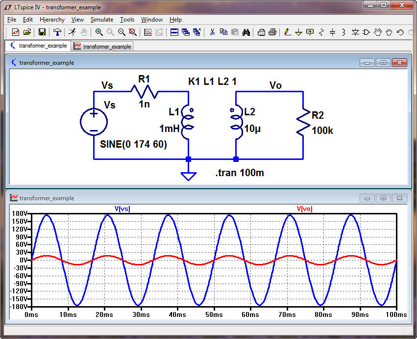
A
transformer can be simulated using transformer_example.asc
(right click to save)
The
negligible resistor, 1 nano ohm, is inserted to ensure that the source
voltage,
Vs, doesn’t drive L1 directly.
The
spice directive (K1 L1 L2 1) is used to specify the coupling between
the
primary, L1, and the second L2 (below 1 or 100%)
Note
that this is NOT a practical transformer for operation at 60 Hz (the
inductances are too small, see comment at the bottom).
Right
clicking on the inductors enables/disables showing the phase dots
(above the
secondary is in phase with the primary).
For
quick reference if Vp
and Ip
are the voltage across, and current through, the primary (L1 above) and
Vs and
Is are the voltage
across,
and current through, the secondary (L2 above) then
Vp/Vs = Is/Ip = Np/Ns
(the easy way to remember this is power, Vp*Ip = Vs*Is)
where
Np and Ns are the number
of turns of wire used in the
primary and secondary wraps around the magnetic core. Also,
Np/Ns = root(L1/L2) = Vp/Vs
So,
above, since L1 is 100 times larger than L2 we expect Vp
to be 10 times larger than Vs (noting we can flip the transformer
around
if we want the output to be larger than the input). Then Ip
is 10 times smaller than Is.
Also,
(Vp*Is)/(Vs*Ip) = Zp/Zs
= (Np/Ns)^2 = L1/L2
Where
Zp is the impedance of
the 100k (= Zs) reflected to
primary (so Zp = 10MEG
here).
Okay,
one last (important) comment related to this simulation, while the
reflected
impedance the primary sees is 10 MEG, and
the
current from this impedance is 174/10MEG or 17.4 uA,
there is still an AC current from the source driving the 1 mH inductor.
This
current, at 60 Hz, has a peak value of 174/(2*pi*60*10^-3) = Vp/(2*pi*f*L)
= 461
A! This current is significantly larger
than
the current due to the transformer action and so this is not a
practical model
for a transformer operating at 60 Hz! To make
the
model more practical (significantly) increase the inductances so this
later
component of current is much smaller than the current
supplied
to the secondary load.