Avalanche Pulser Circuit
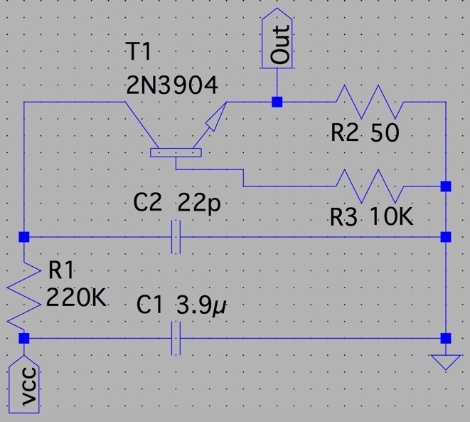
Schematic
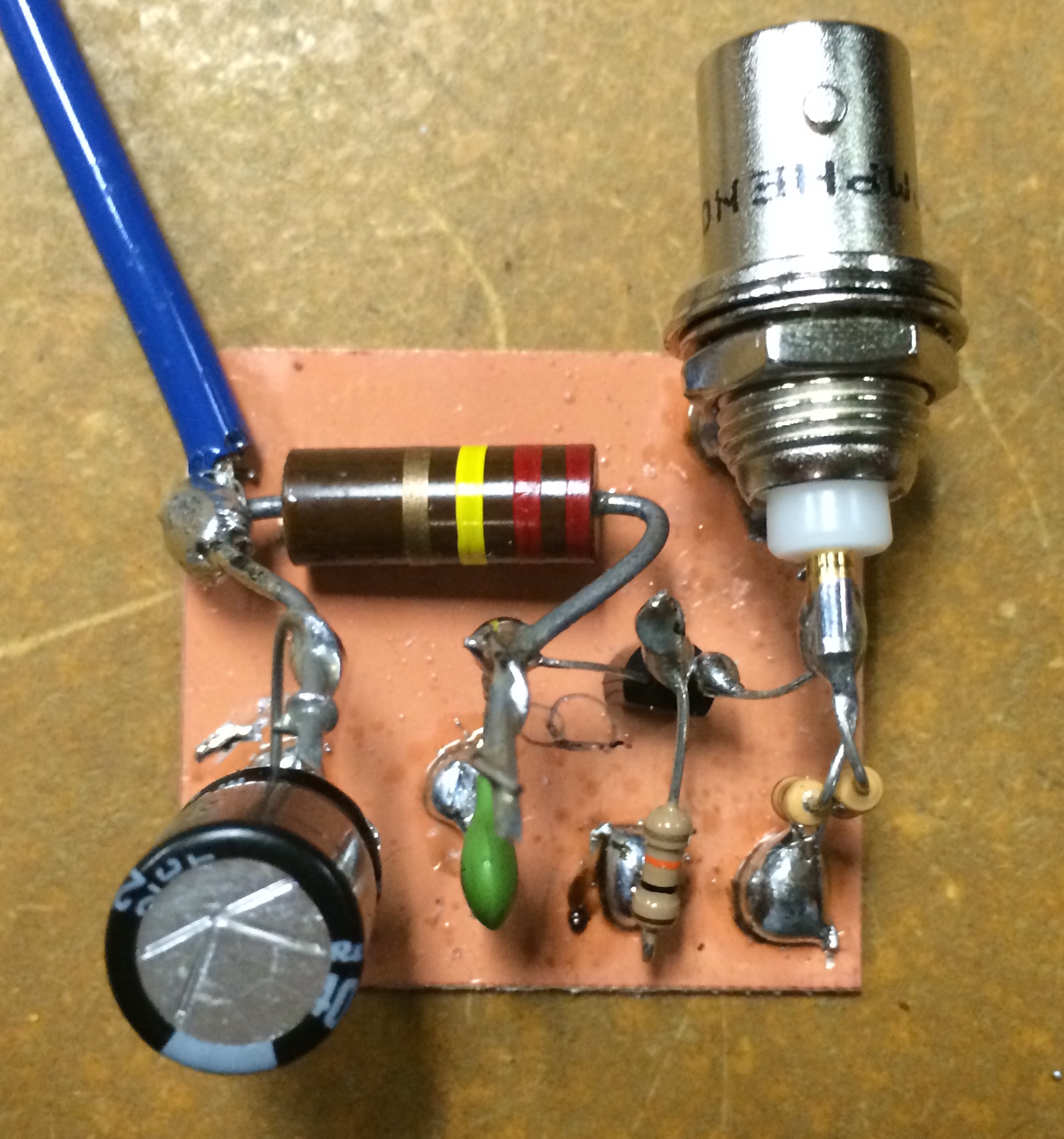
DeadBug Prototype
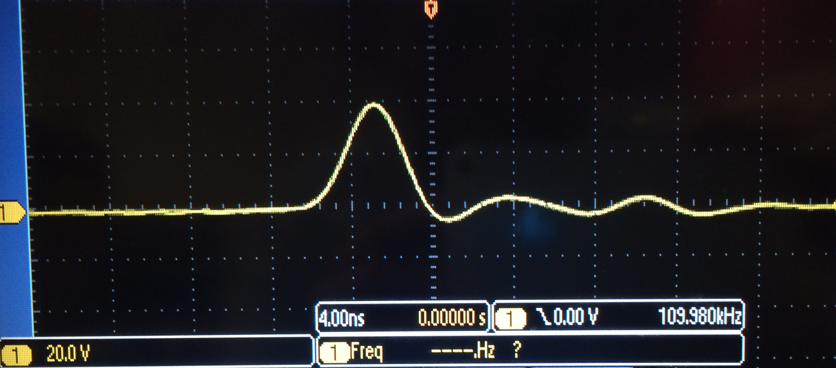
Output and Performance
During
the first test of the Avalanche Circuit, a 100MHz digital oscilloscope
was used to measure the voltage output of the circuit.
The Circuit showed a 40 V output.
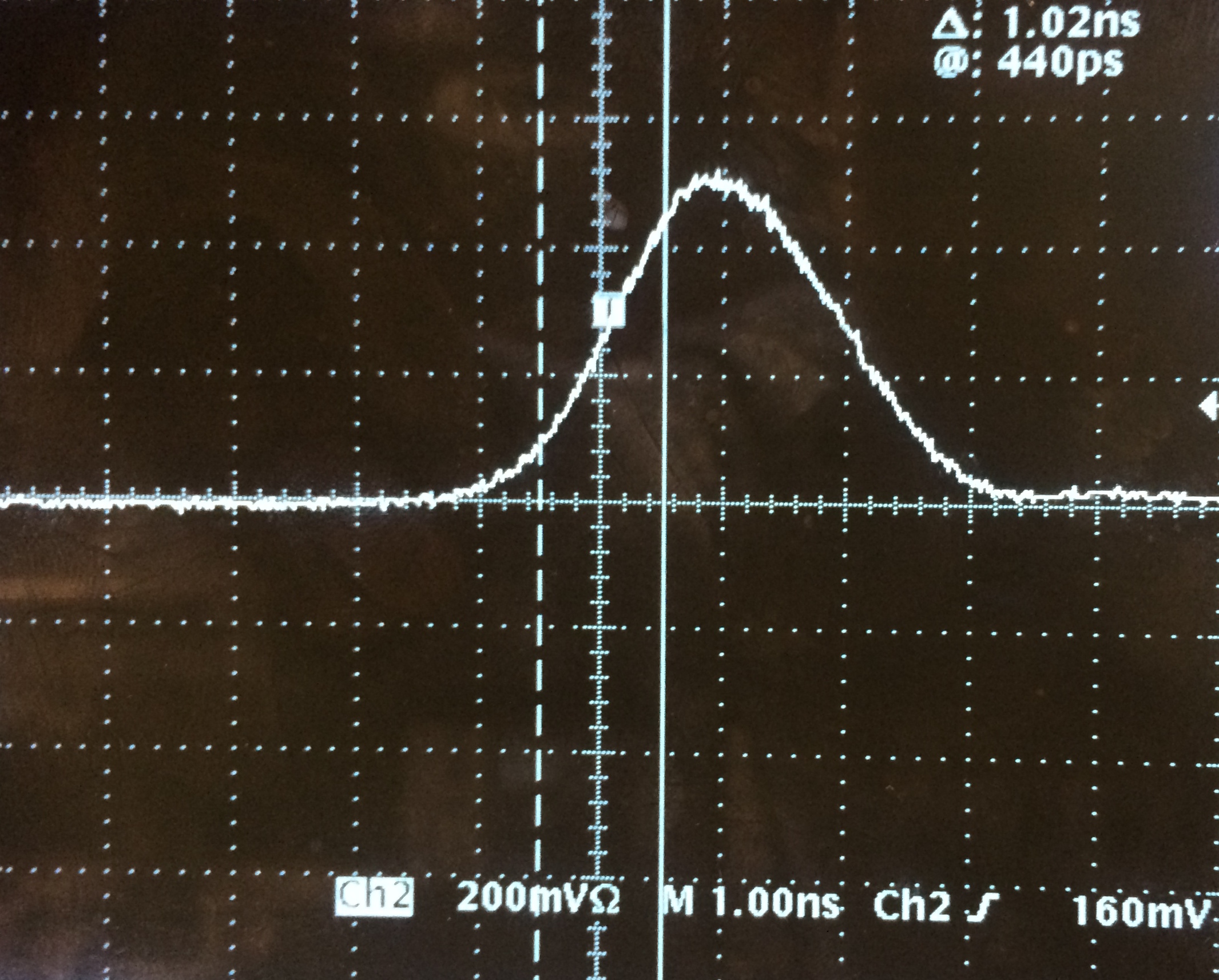
The circuit was then tested using a 500MHz oscilloscope. With the same 120 V input the circuit produced 50 V this time.
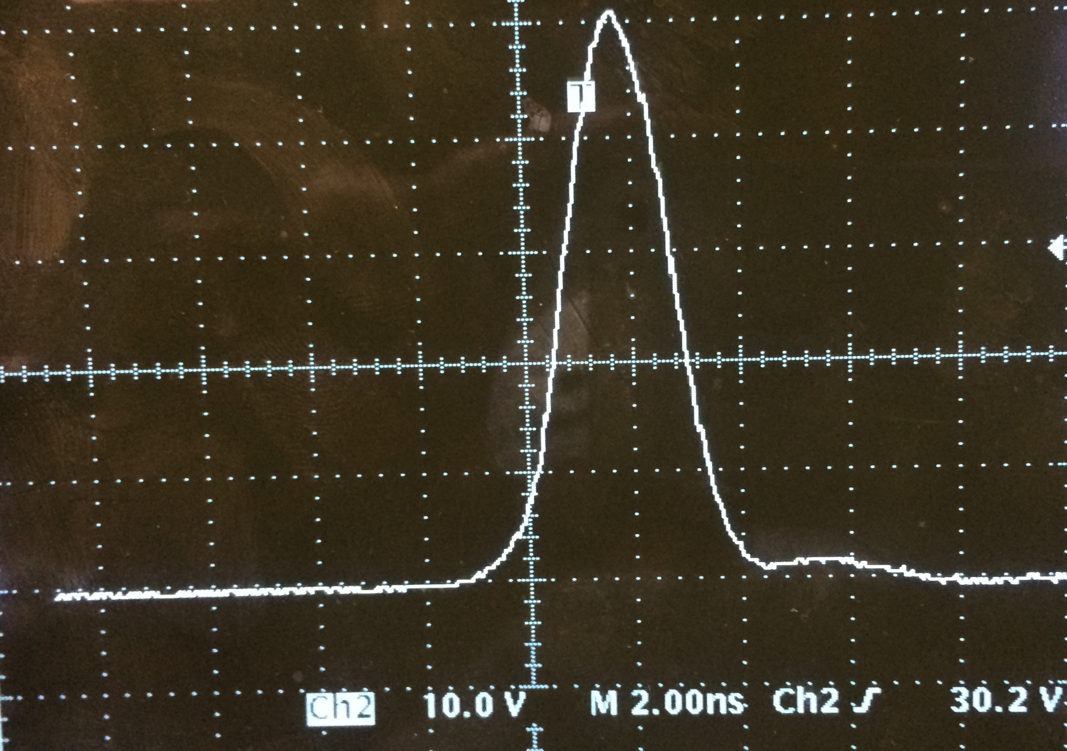
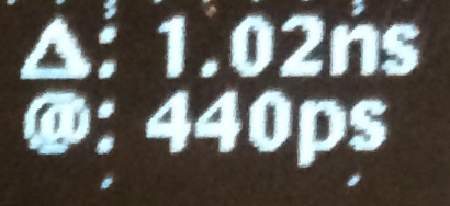
Lastly using the same oscilloscope we measured a 1.02 ns rise time.
Return